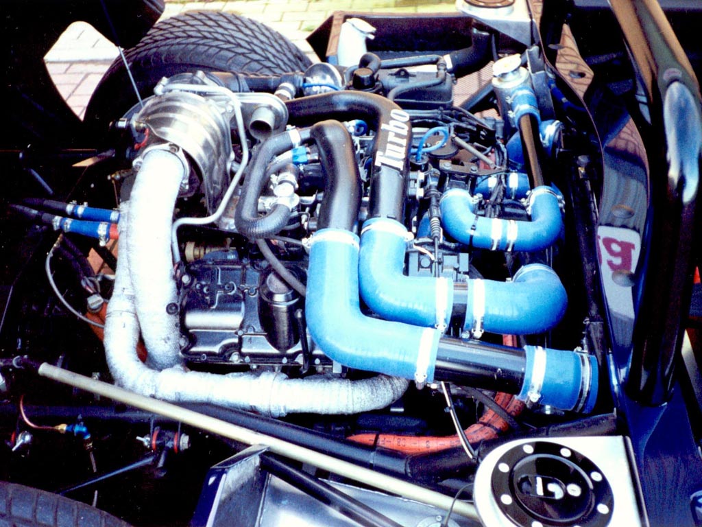
I built this Spyder back in 1997 with a Renault 25 V6 Turbo motor & UN1 Gearbox.
It was good and I was a fairly early adopter of building a kit car with an EFI motor, especially turboed.
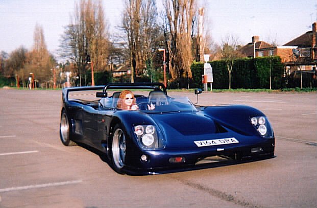
It always ran well – but time passes and I decided a few years back to re-engine it.
I bought an engine, gearbox, custom flywheel & clutch for it – and then parked it for another few years…
Getting Started
Roll on 2021 and I decided I really must make a start on actually doing this conversion. So I now had:
- an AHC Audi V8 Motor
- and a GVC 01X G-speed Box
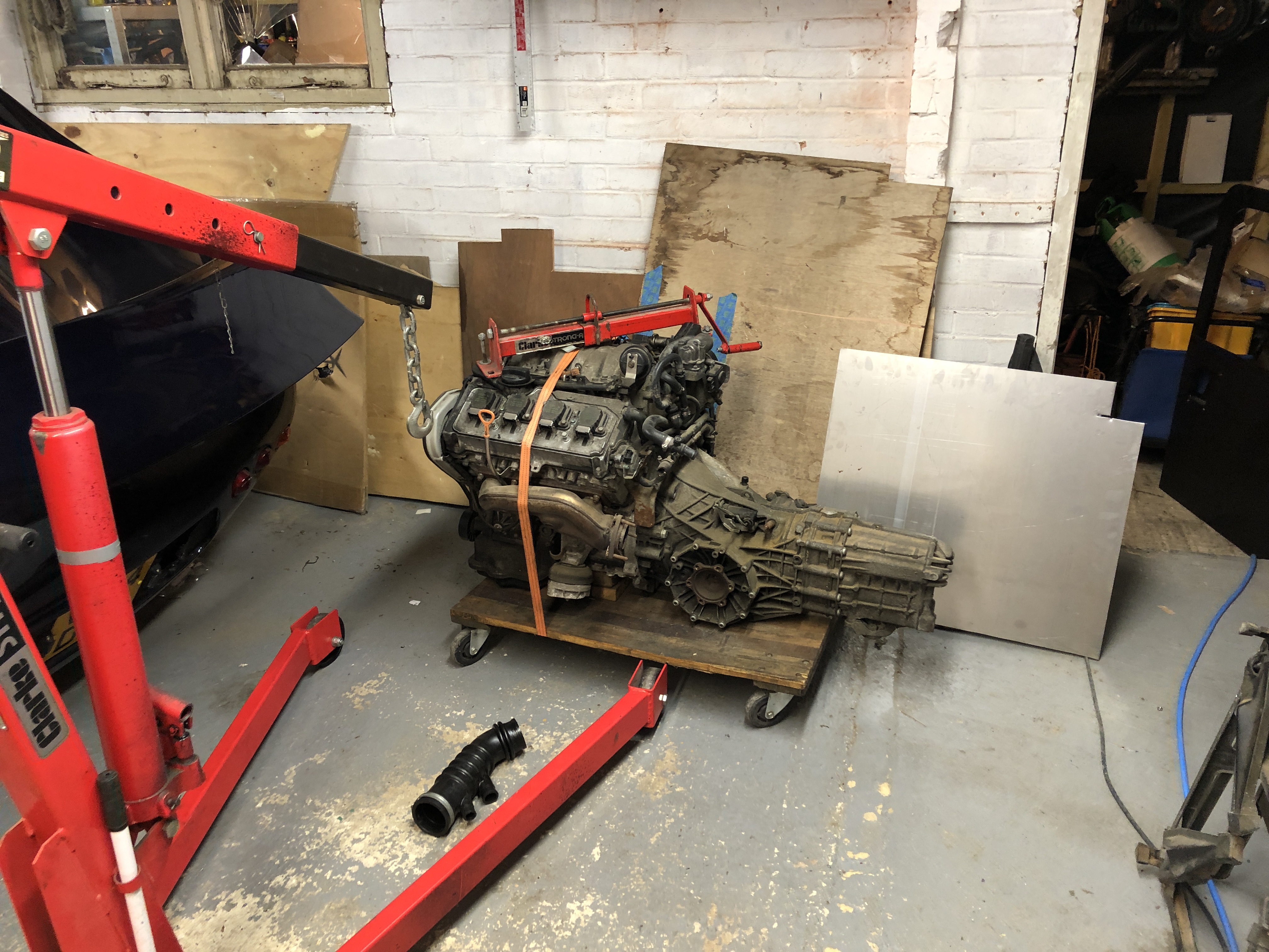 Time to take the old engine out:
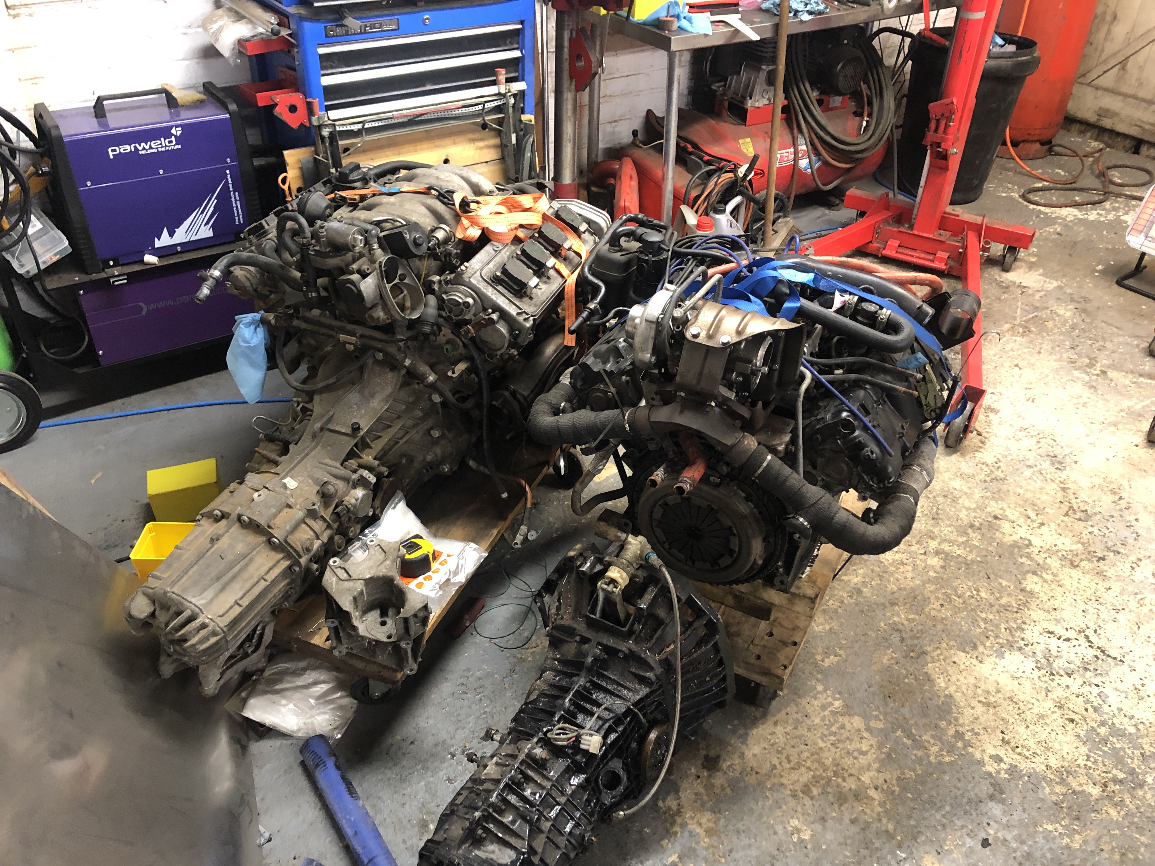
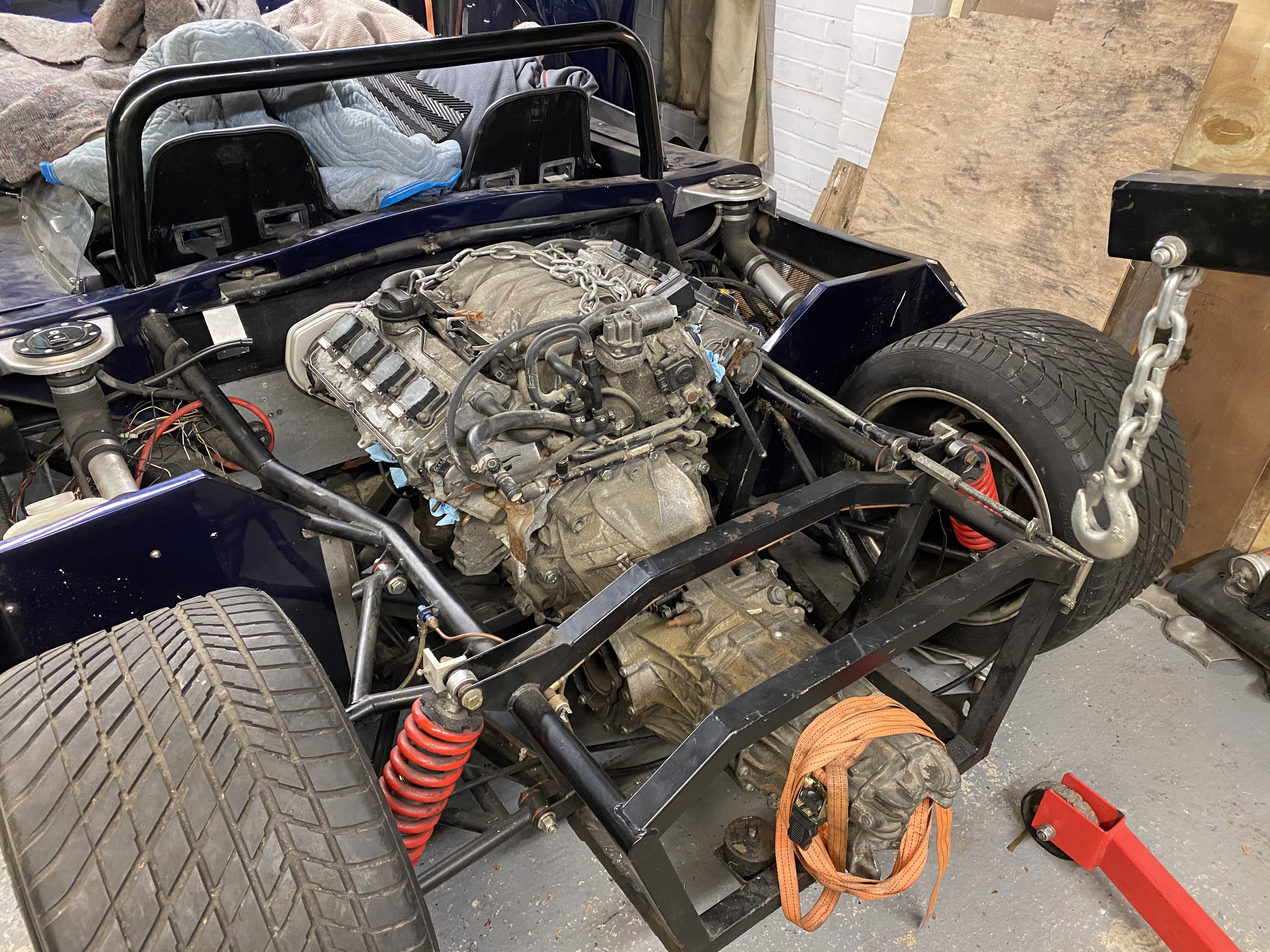
 Almost twice the horsepower, but hardly any bigger:
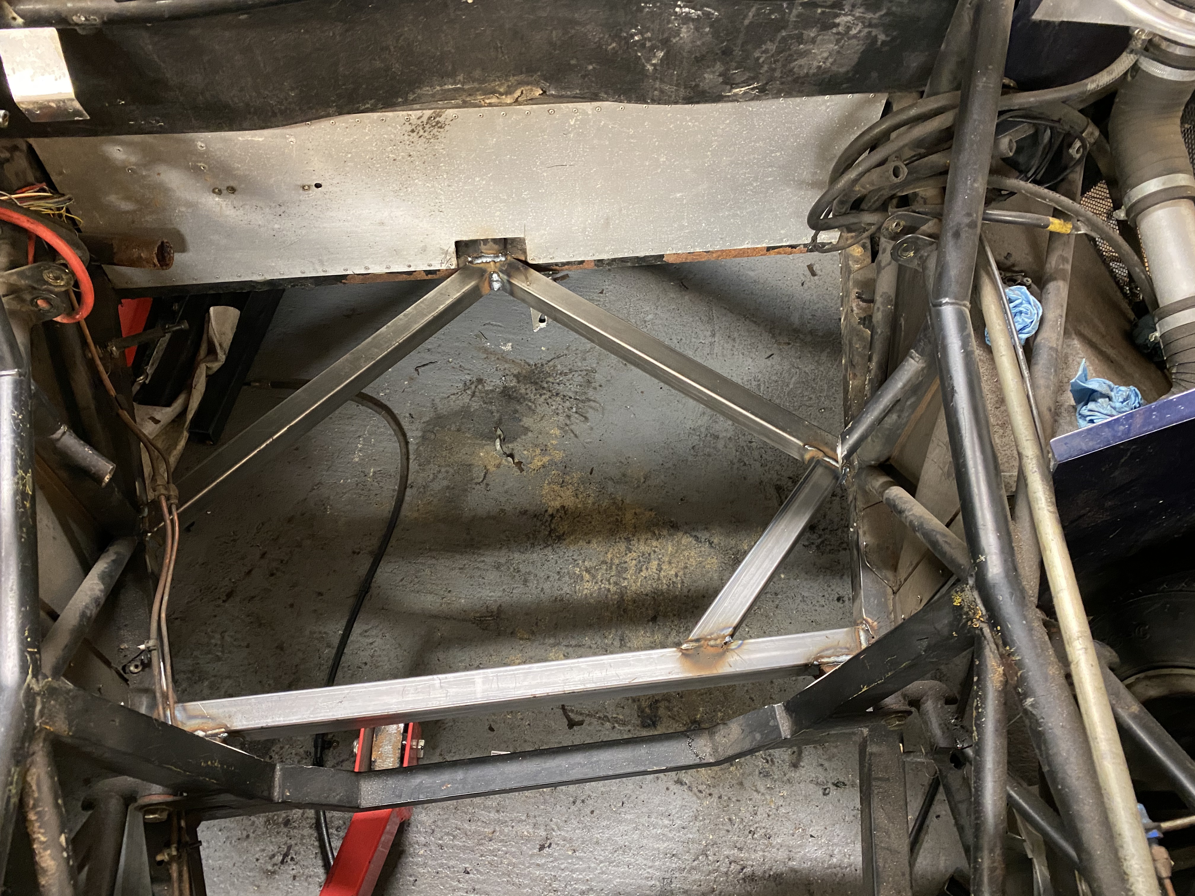
Chassis Modifications.==
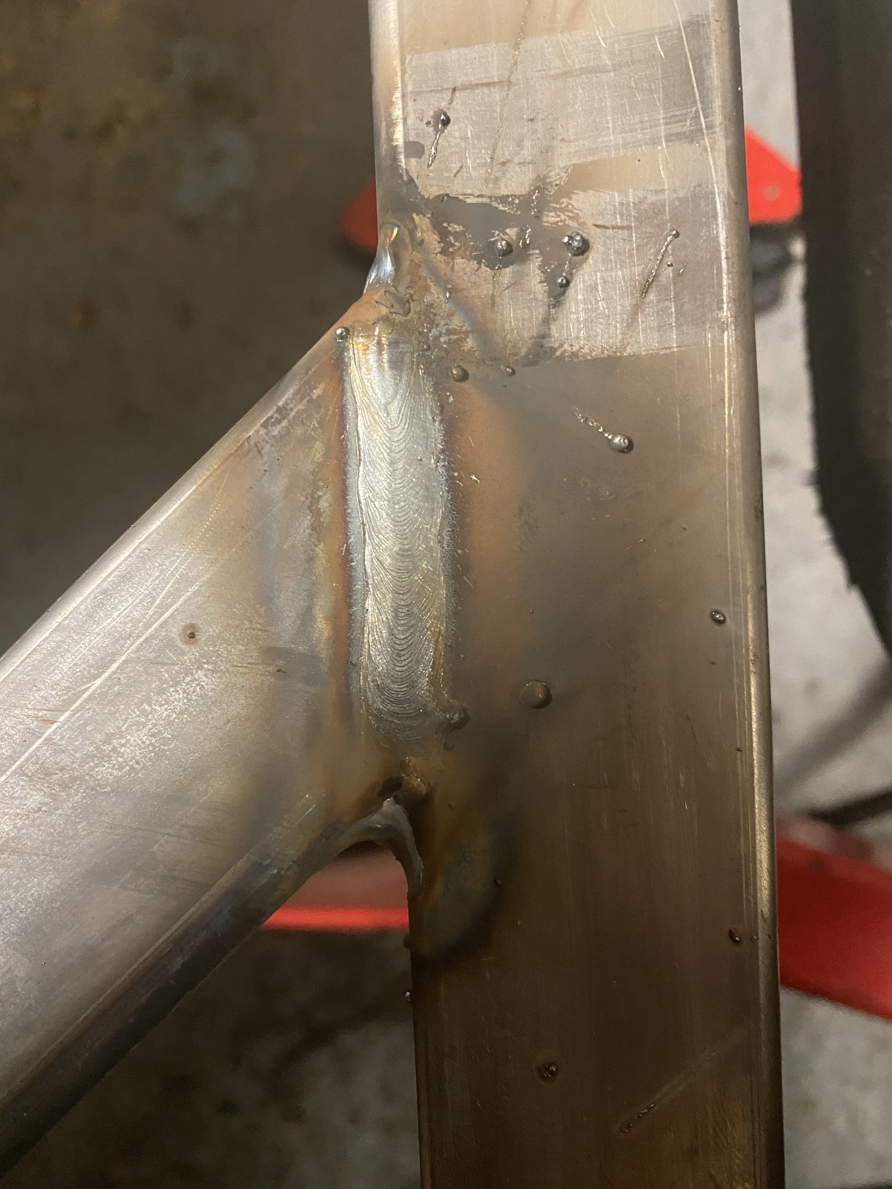
Still learning the new welder, but seemed to go OK:
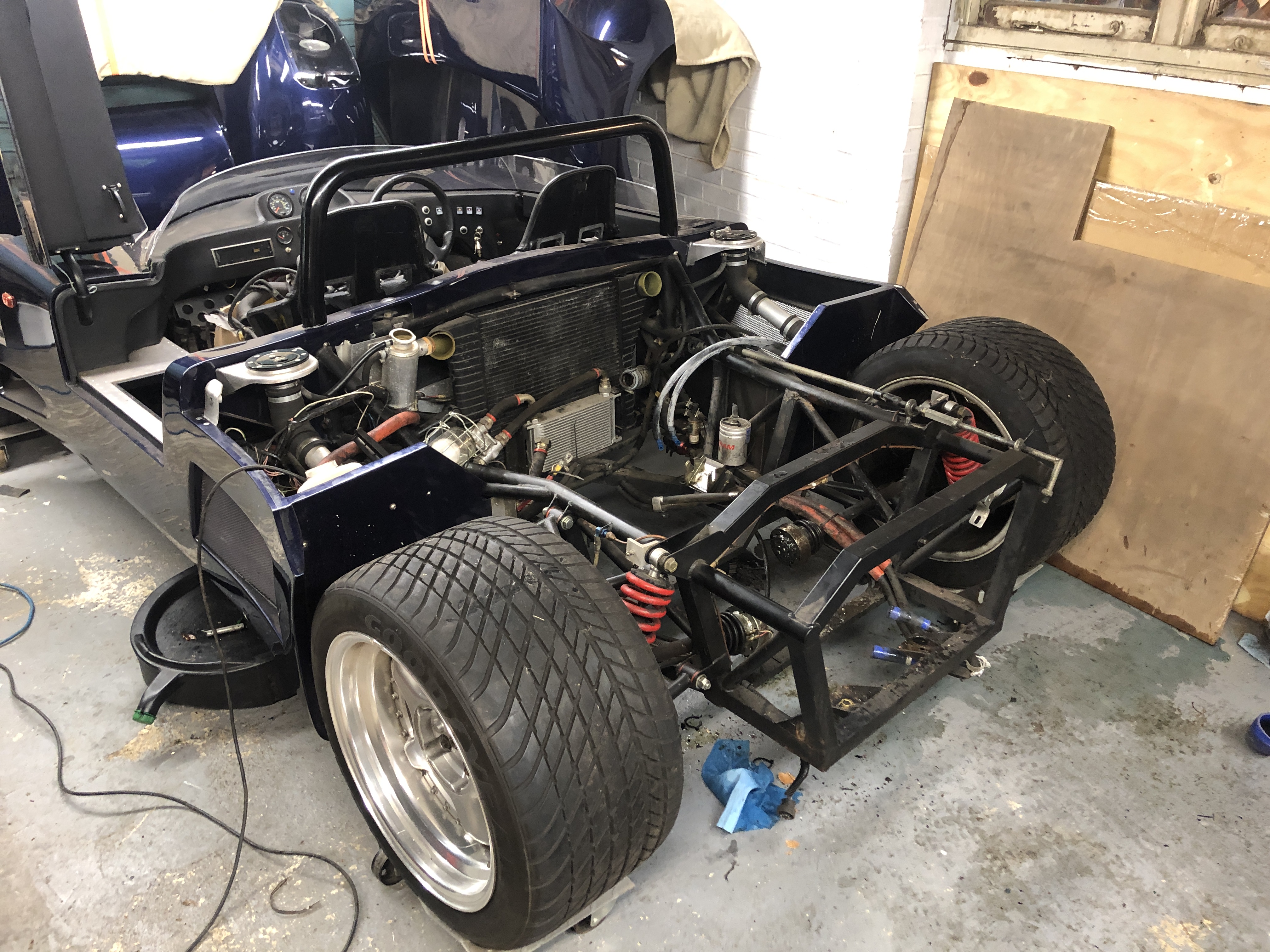
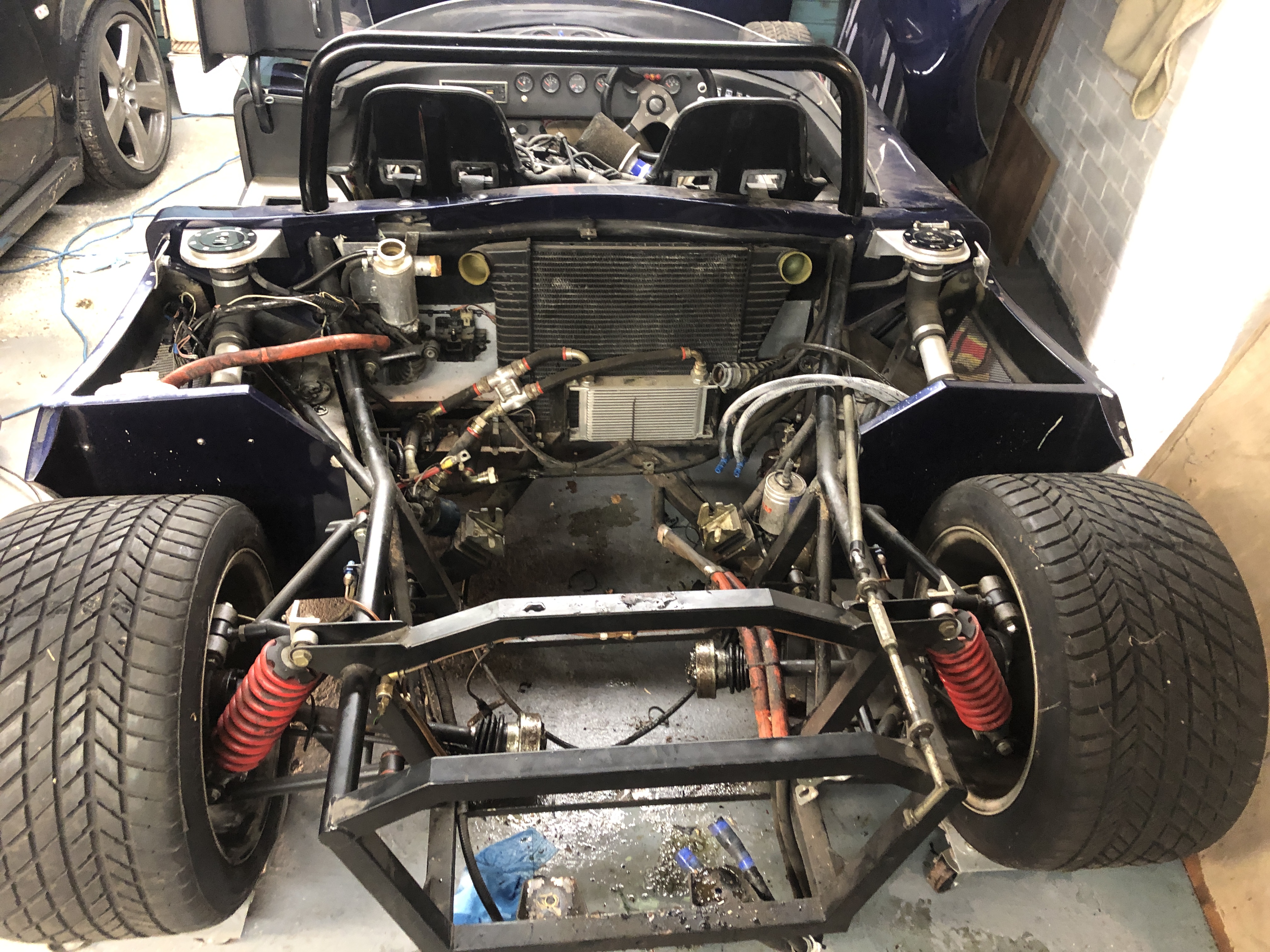
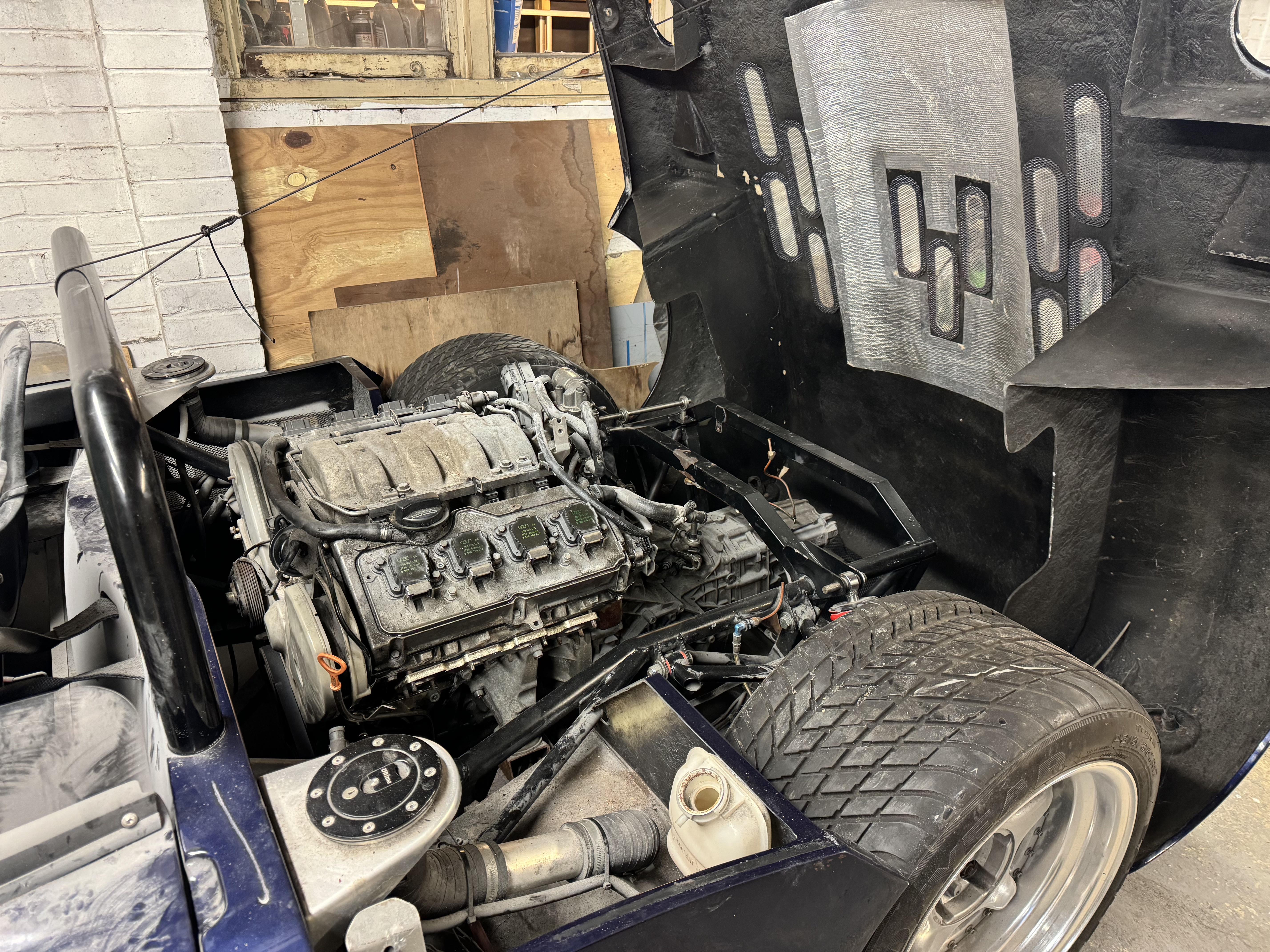
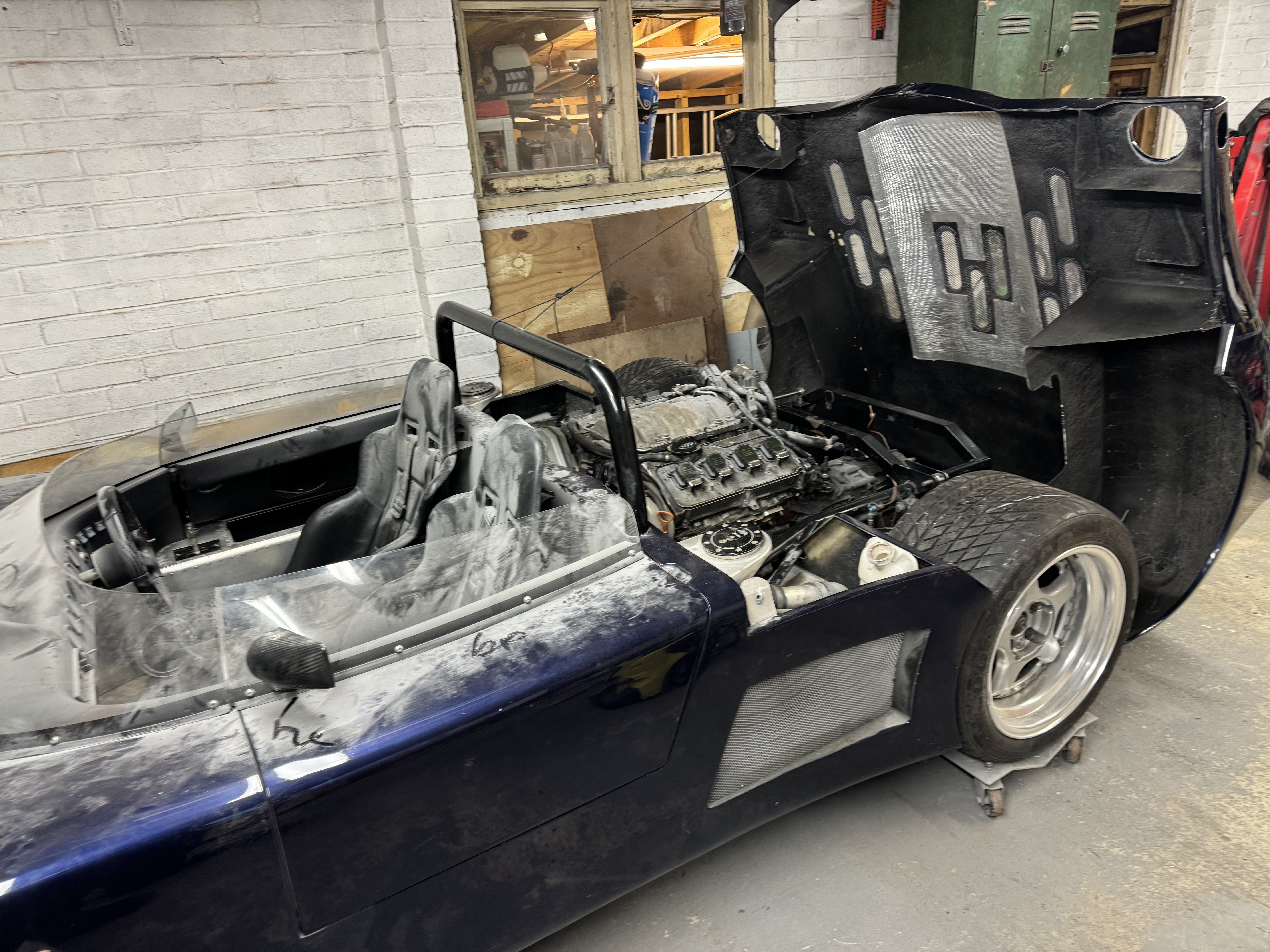
Engine looks like it was made to fit, good clearance all round on the chassis and body – which is excellent, I don’t think anyone has tried to squeeze one of these motors in to a spyder before, they have less hood clearance than the sports/gtr/can-am. Sump protudes about 15mm out the bottom – which is a less than the old motor did and also shed loads less than a SBC would.
The motor was sitting on wooden blocks in the new chassis in this pic while we check clearances:
 Next step, steel on order to make the engine mounts next, just waiting on order to arrive and will wheel out the welder again, while I ponder gear linkages as well.
Gear linkage was a proper chin scratcher to try and K.I.S.S, but I had a plan.
Next step, steel on order to make the engine mounts next, just waiting on order to arrive and will wheel out the welder again, while I ponder gear linkages as well.
Gear linkage was a proper chin scratcher to try and K.I.S.S, but I had a plan.
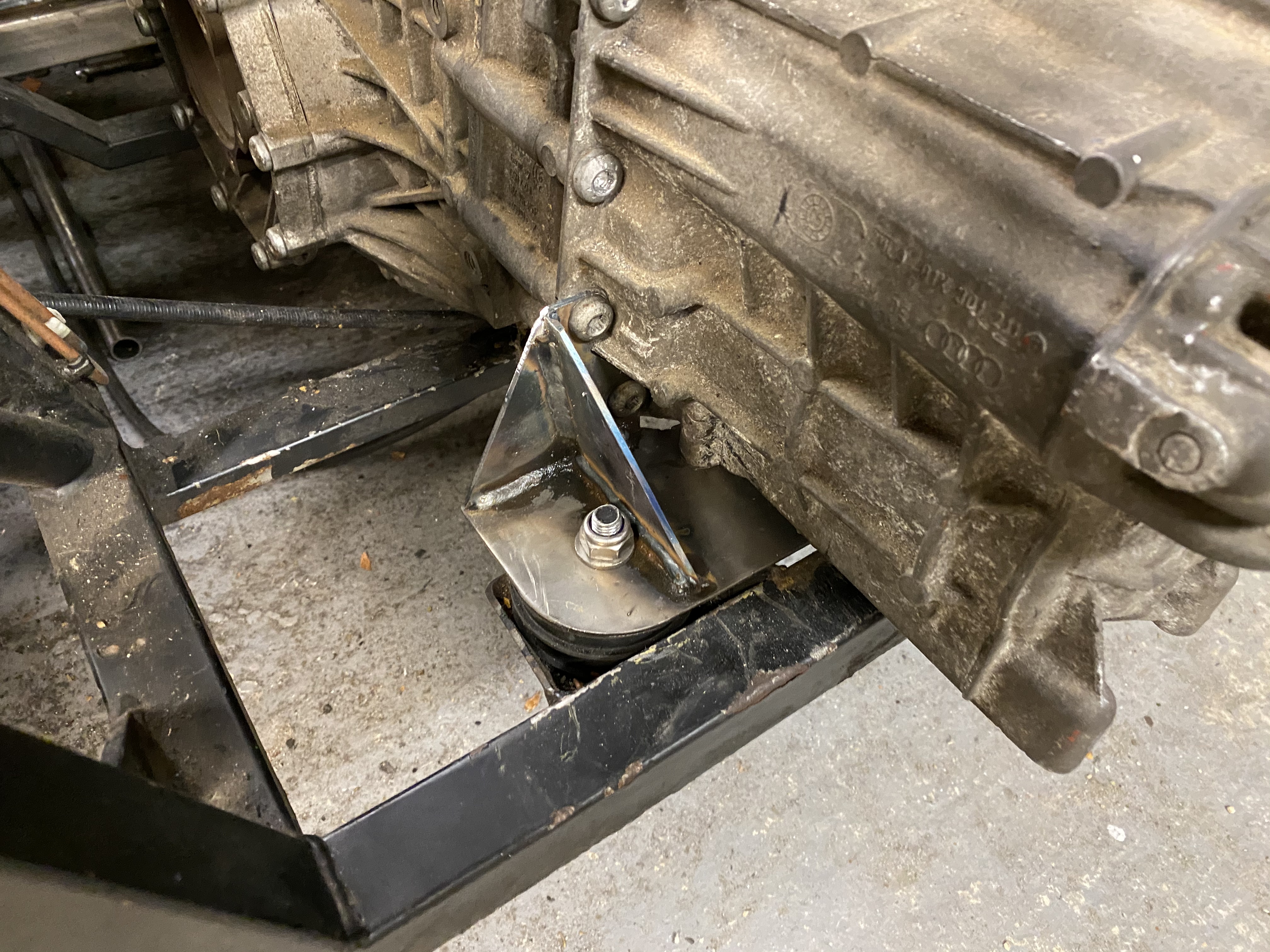
Chassis mods were completed along with engine & gearbox mounts.
Christmas 2023 – Gear Linkage
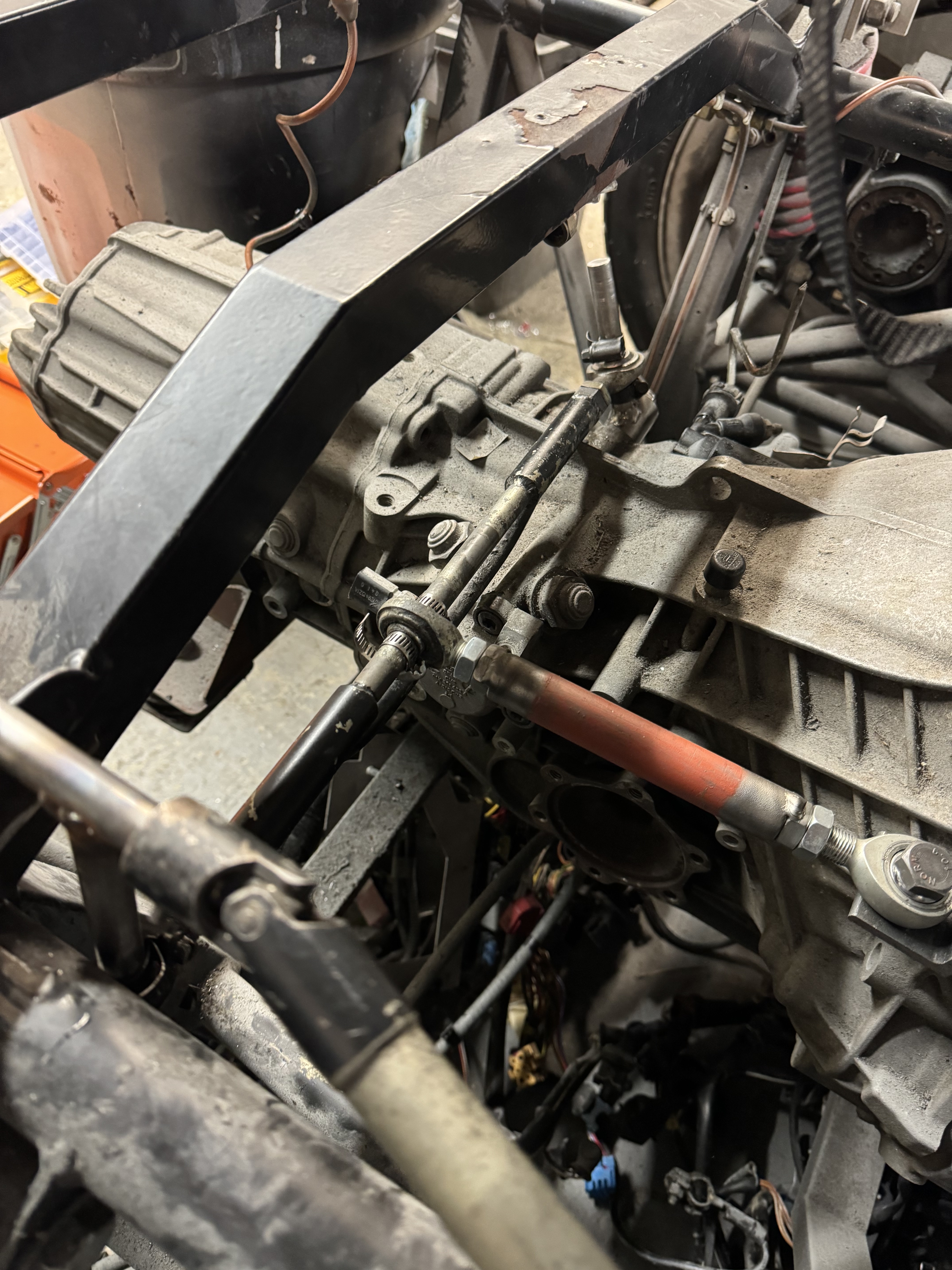
With a far too long hiatus, I spent some time over christmas doing the gear linkage. It’s just mocked up for now (hence jubilee clips and over-length rods), but works really well and all gears fit in the perfectly.
The gearbox end – the “lever” that makes it all happen. Will be shortened eventually:
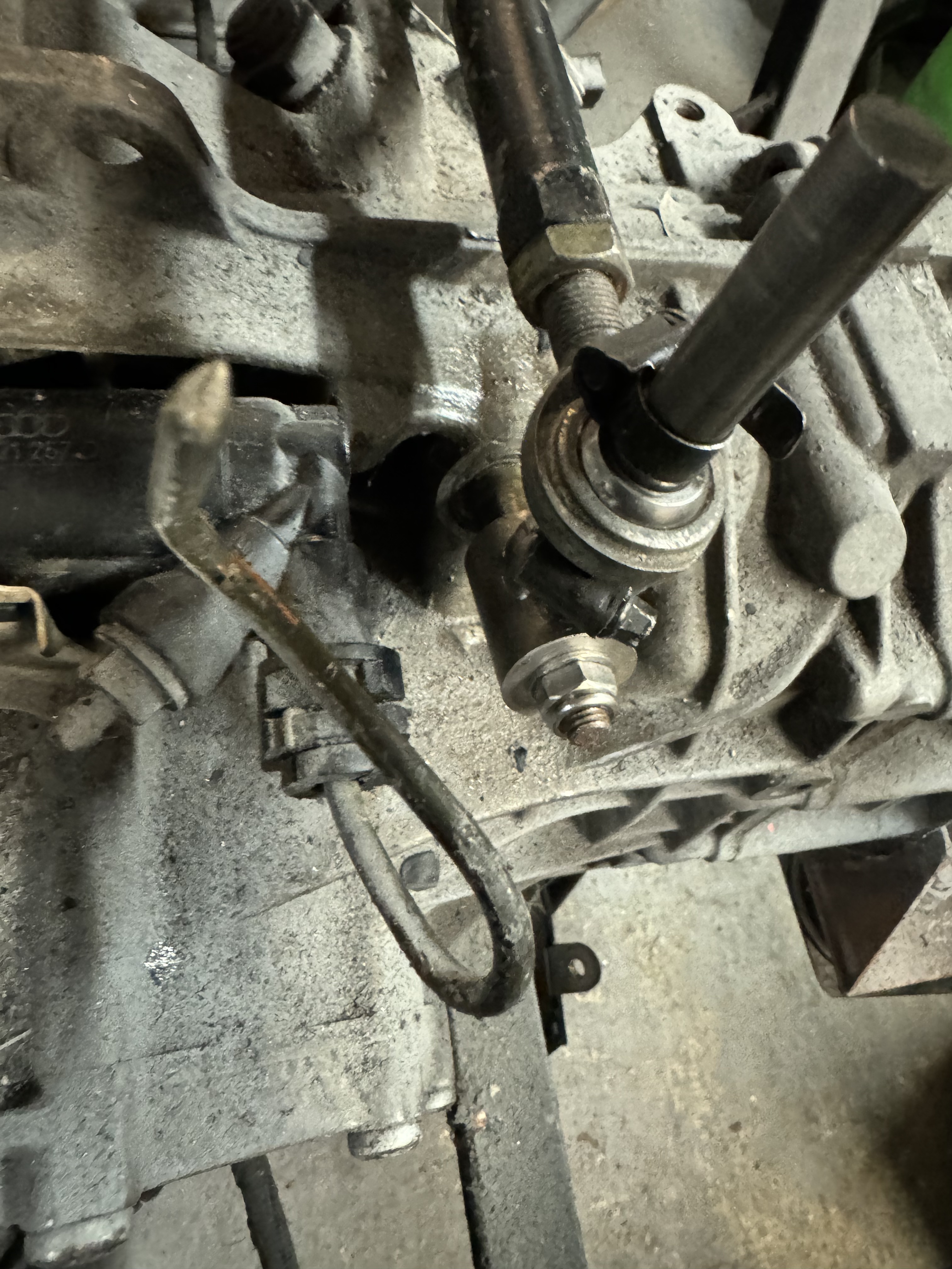 Detail of the shifter bar. I reused as much as I could of the old UN1 linkage mechanism – although the audi box shifts the other way round entirely:
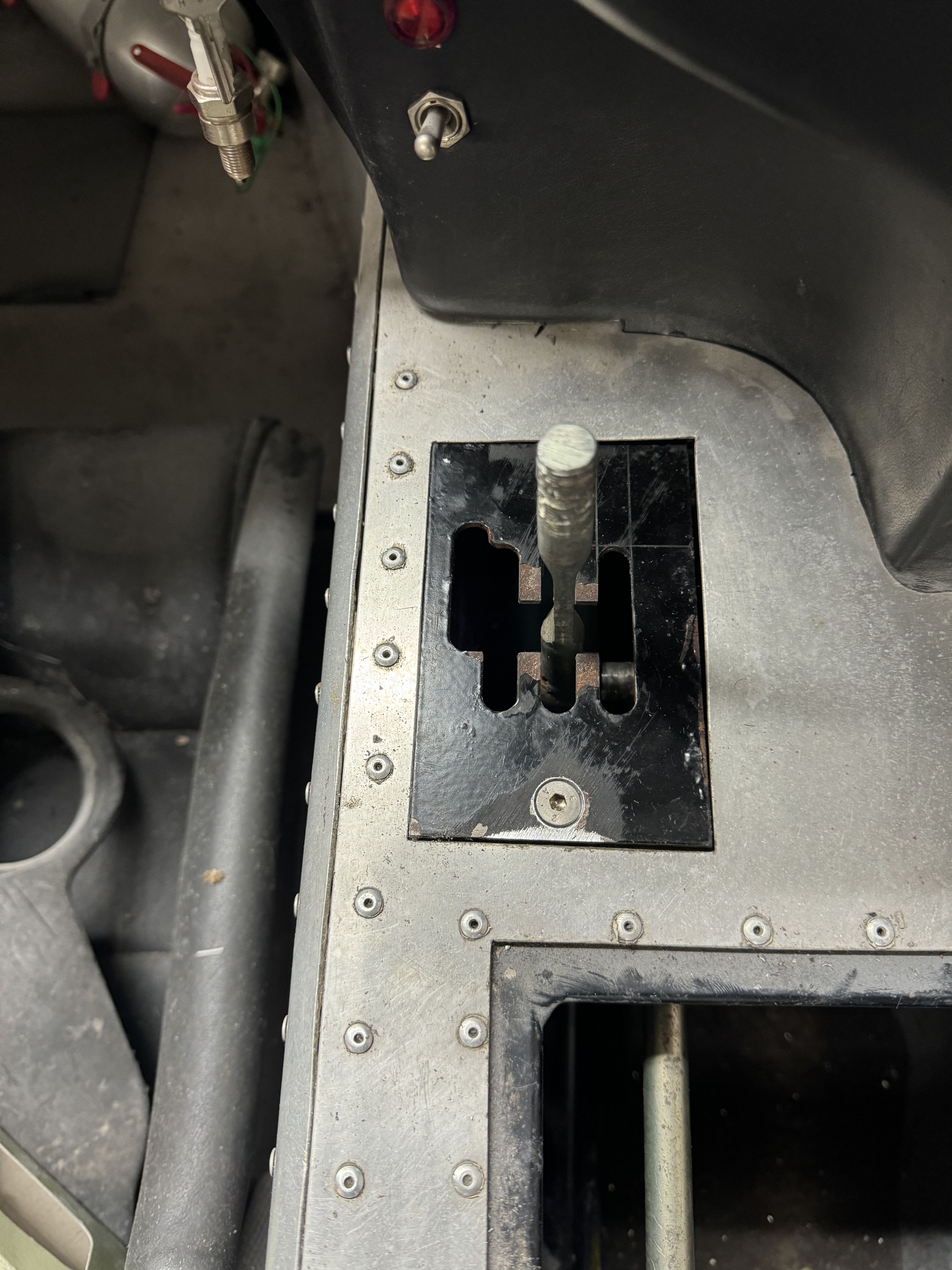
 But it seems to work. I cut the old gate around a bit just to see if it would all work, will probably get a nice laser cut one eventually:
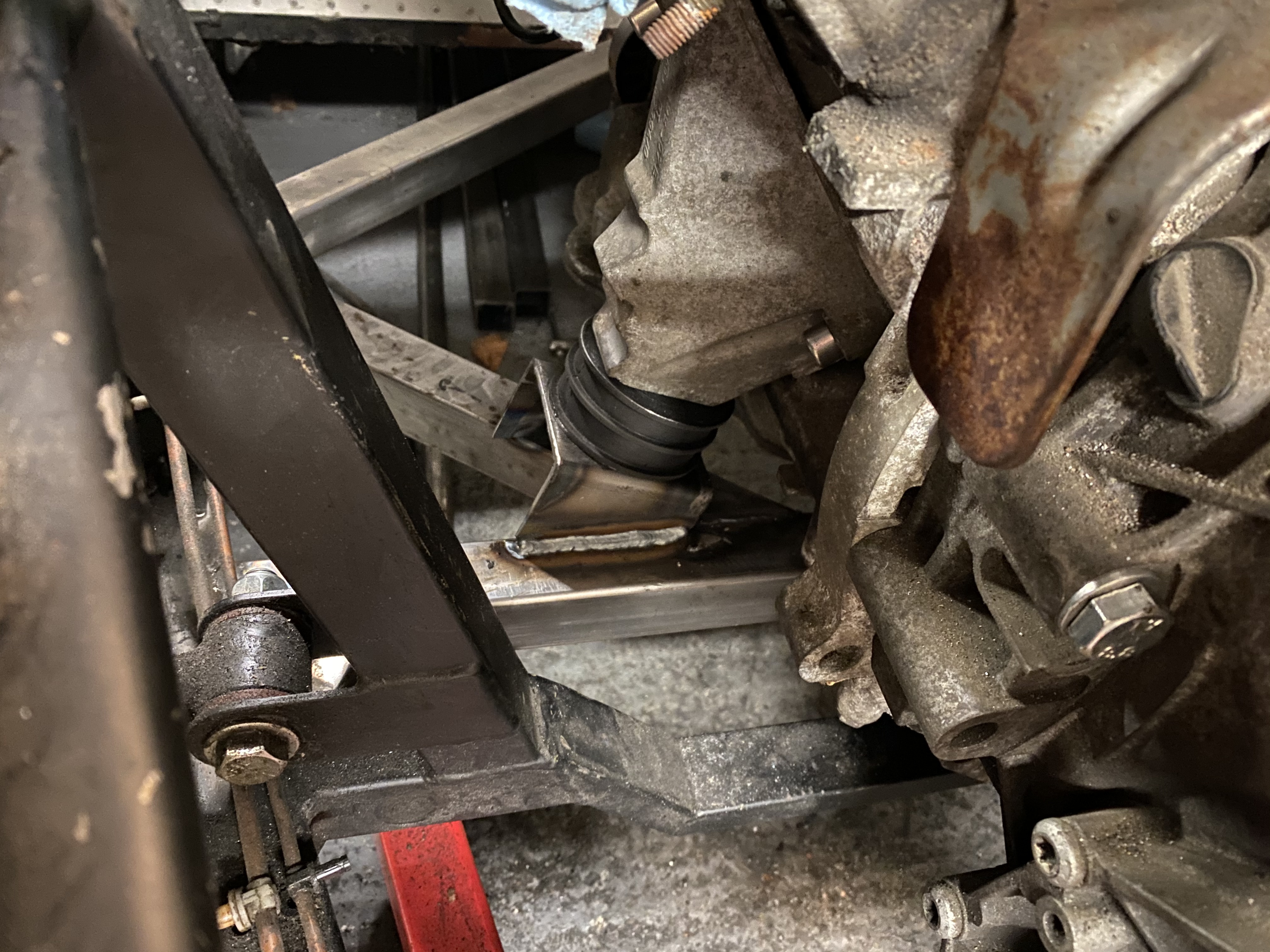
Driveshafts
Then the CV Joints arrived so I spent a bit of time mocking up the first driveshaft with some 25mm tube.
When designing the engine & gearbox mounts, I spent a lot of time making sure the engine was as far forward and as low down as I could make it, which you can see from the driveshaft angles.
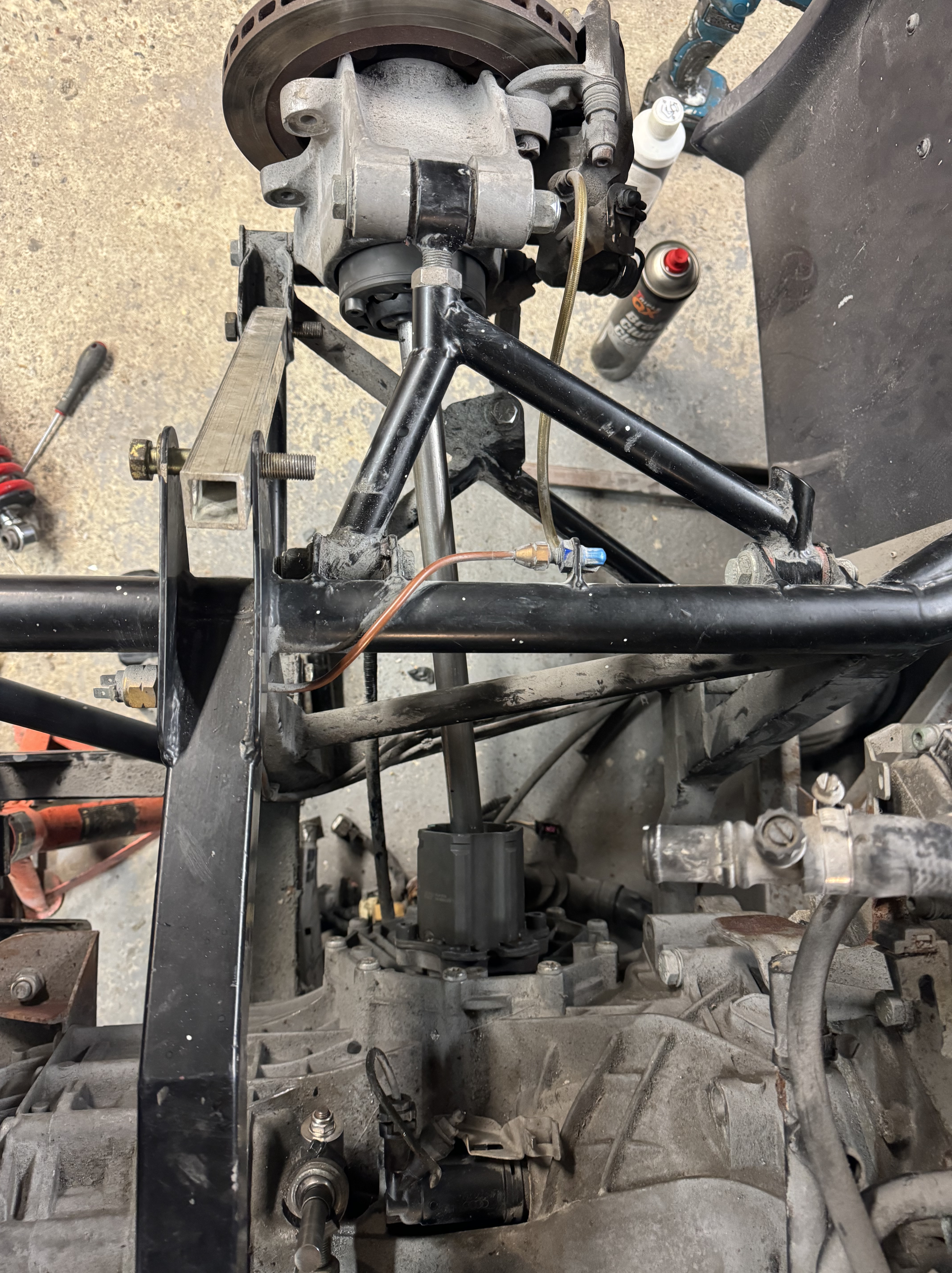
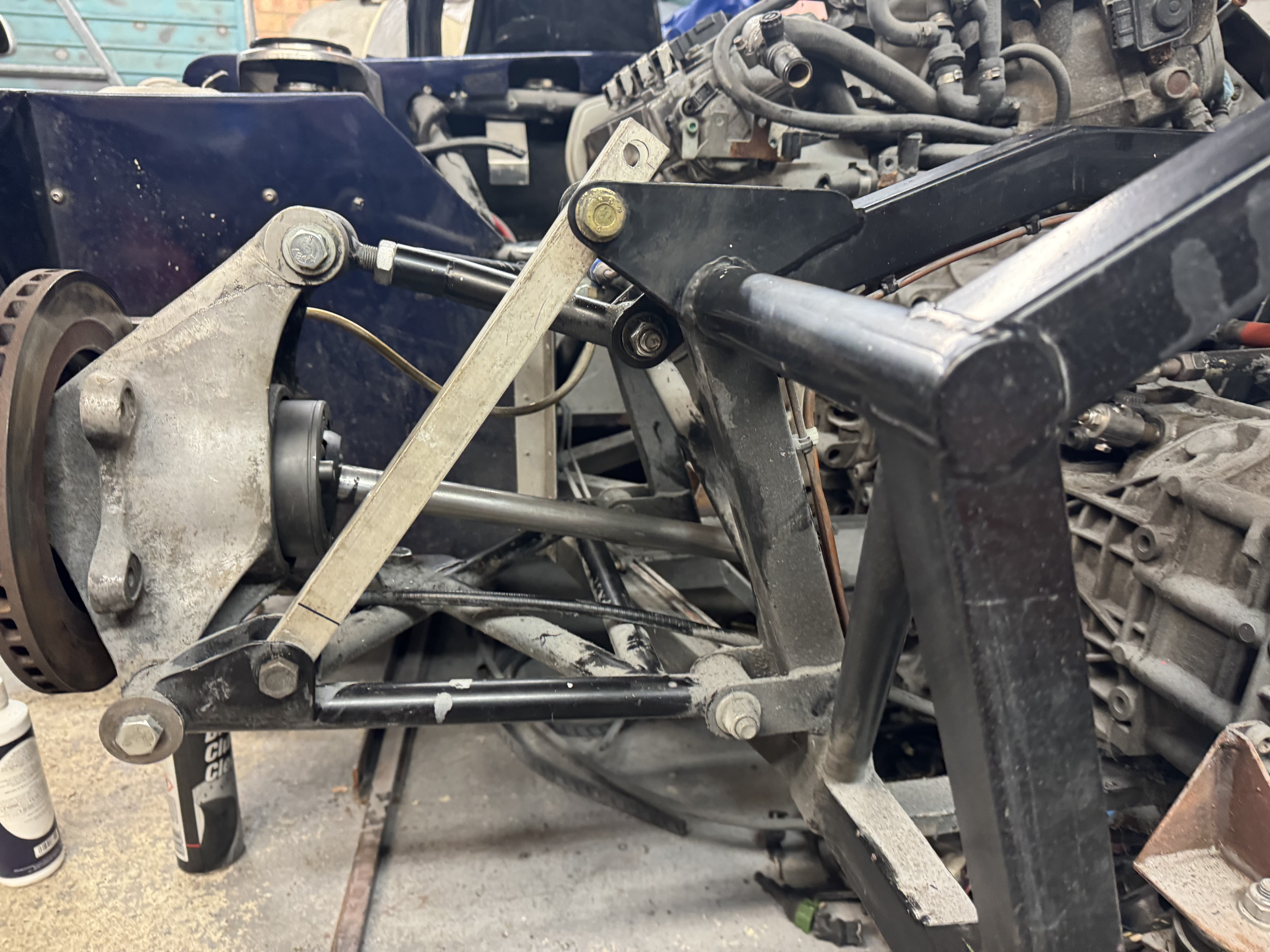
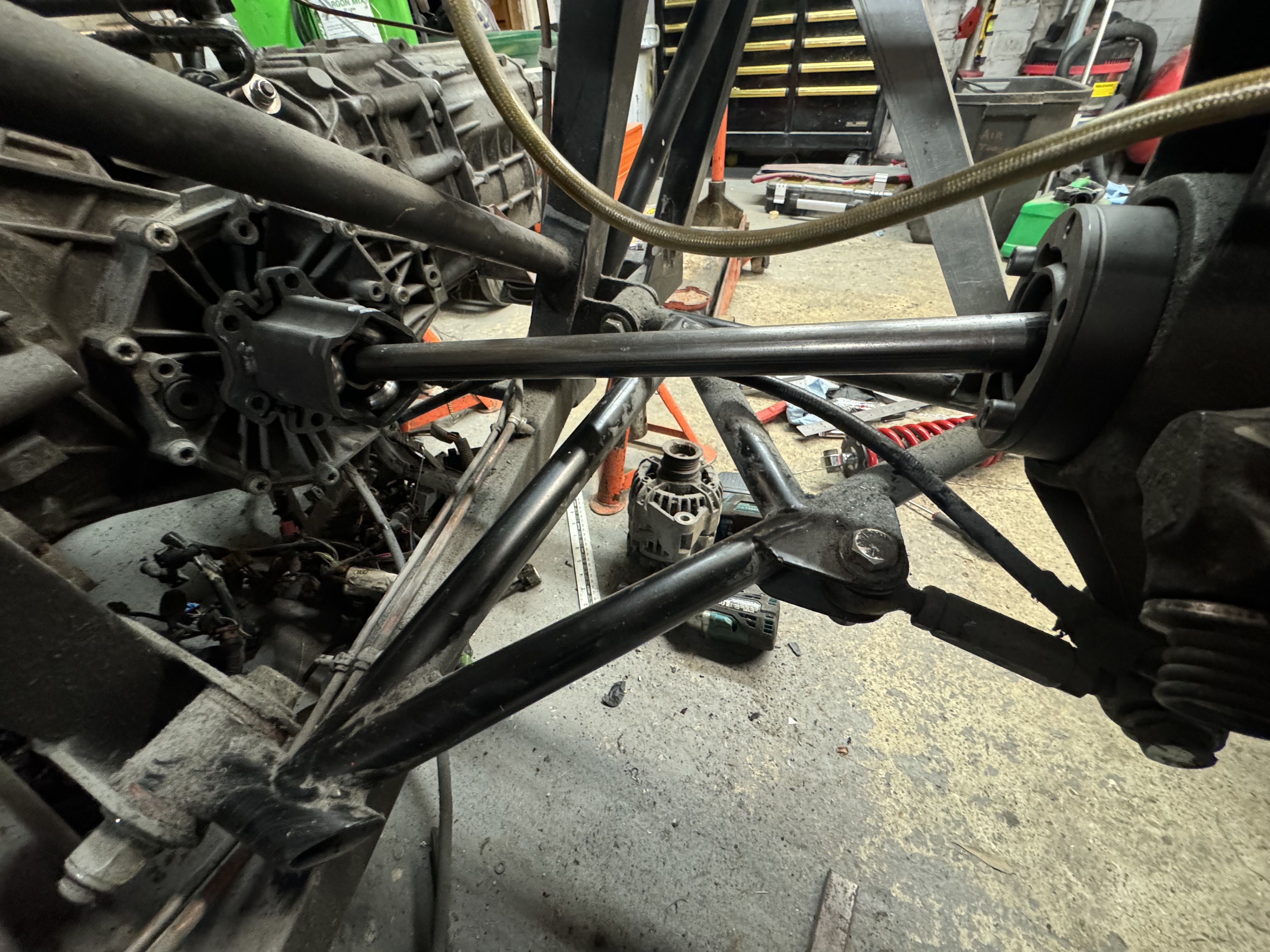 There’s at least 19mm of possible movement (at full drop) on the driveshaft, and 23mm movement resting height, and 22mm on the bump stops. So nothing bottoms out.
As of Feb 24, I’m waiting for the driveshafts to arrive. 🙂
There’s at least 19mm of possible movement (at full drop) on the driveshaft, and 23mm movement resting height, and 22mm on the bump stops. So nothing bottoms out.
As of Feb 24, I’m waiting for the driveshafts to arrive. 🙂
Alternator mounts.==
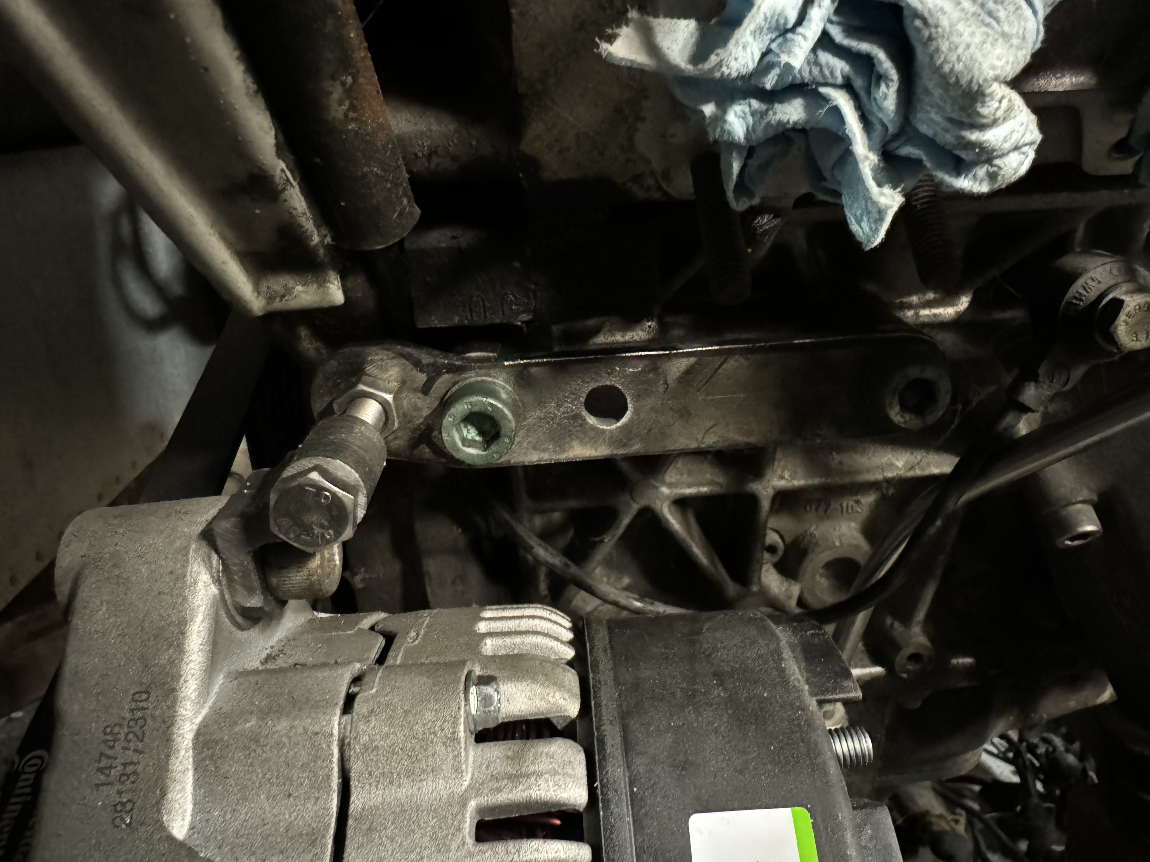
I tried quite hard to mount the alternator on the OS of the car, modifying the original mount. But I’ve actually mounted the engine so low in the chassis that the alternator fouled. Obviously some of what I am doing is inspired by “Hilly’s” Lotus that you can find on motorgeek – esp using the 01x and Audi V8 motors together – and in this case, had to switch the alternator to a NS mount like his. However. my engine mounts are completely different to his – and therefore so is my alternator mount which is a standalone unit. Even considered using a different (smaller) alternator, but couldn’t easily find one that I could be sure would be easier to fit, and I had this one on the shelf already/
I also did away with the automatic tensioner design and have just gone with manual adjustment for the sake of simpler fabrication (this version version 3 already – V1 was modifying the original, then I made a V2 to trial the OS fitment and worked out all the measurements to get it spot on – and then based on lessons from that I did V3!). But I think it all came out OK and if I have to adjust the belt tension every couple of years – no big deal!
OS one that didn’t quite work:
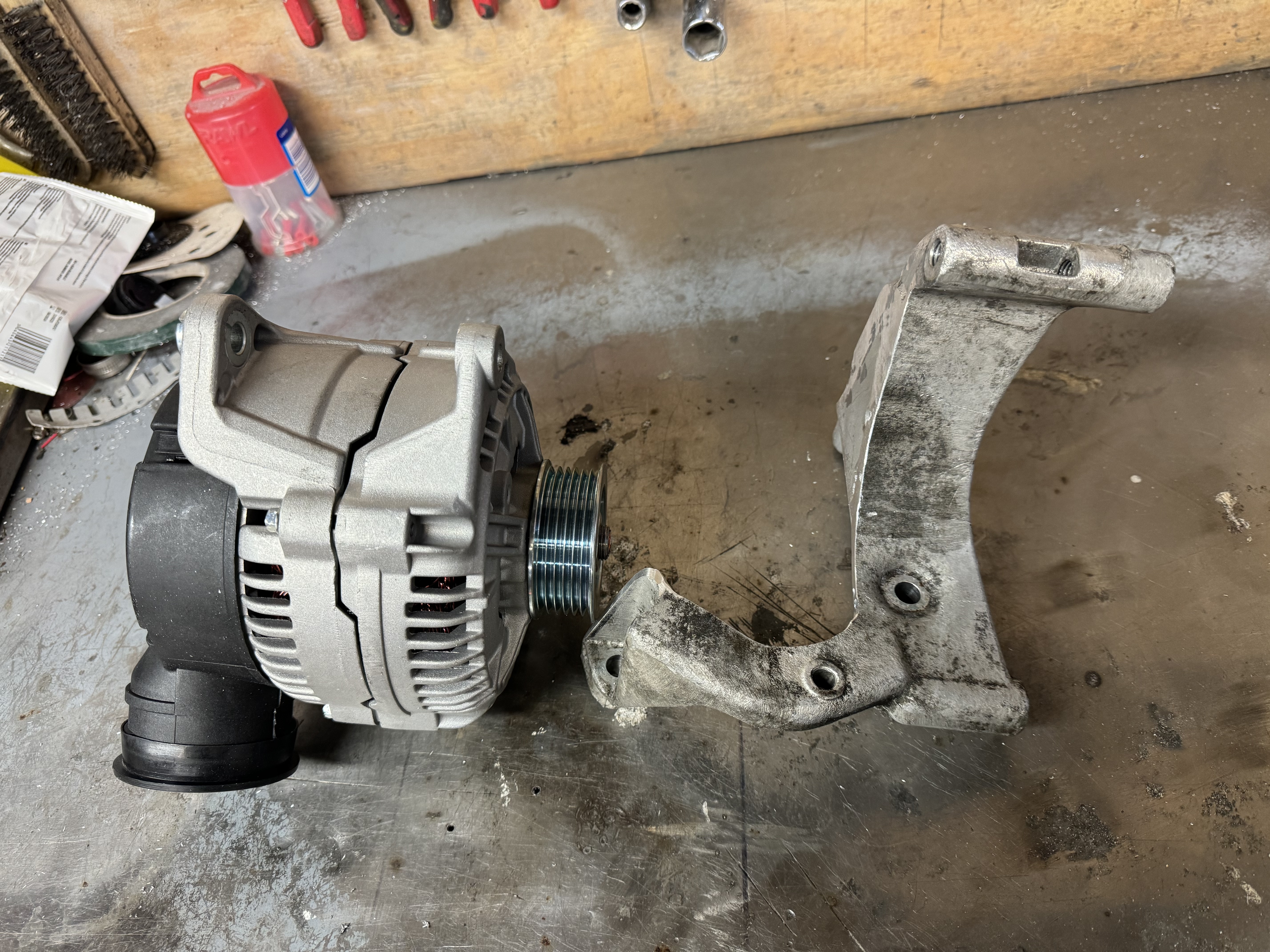
You can just about see the bottom mount here. Forgot to take a decent pic of it on it’s own.
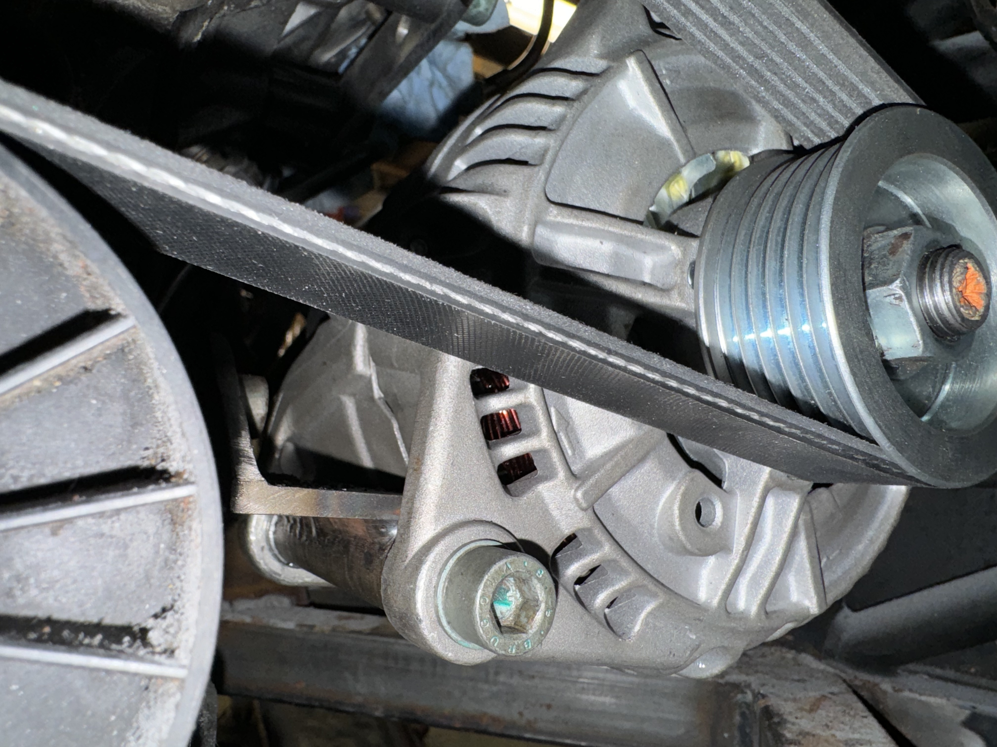
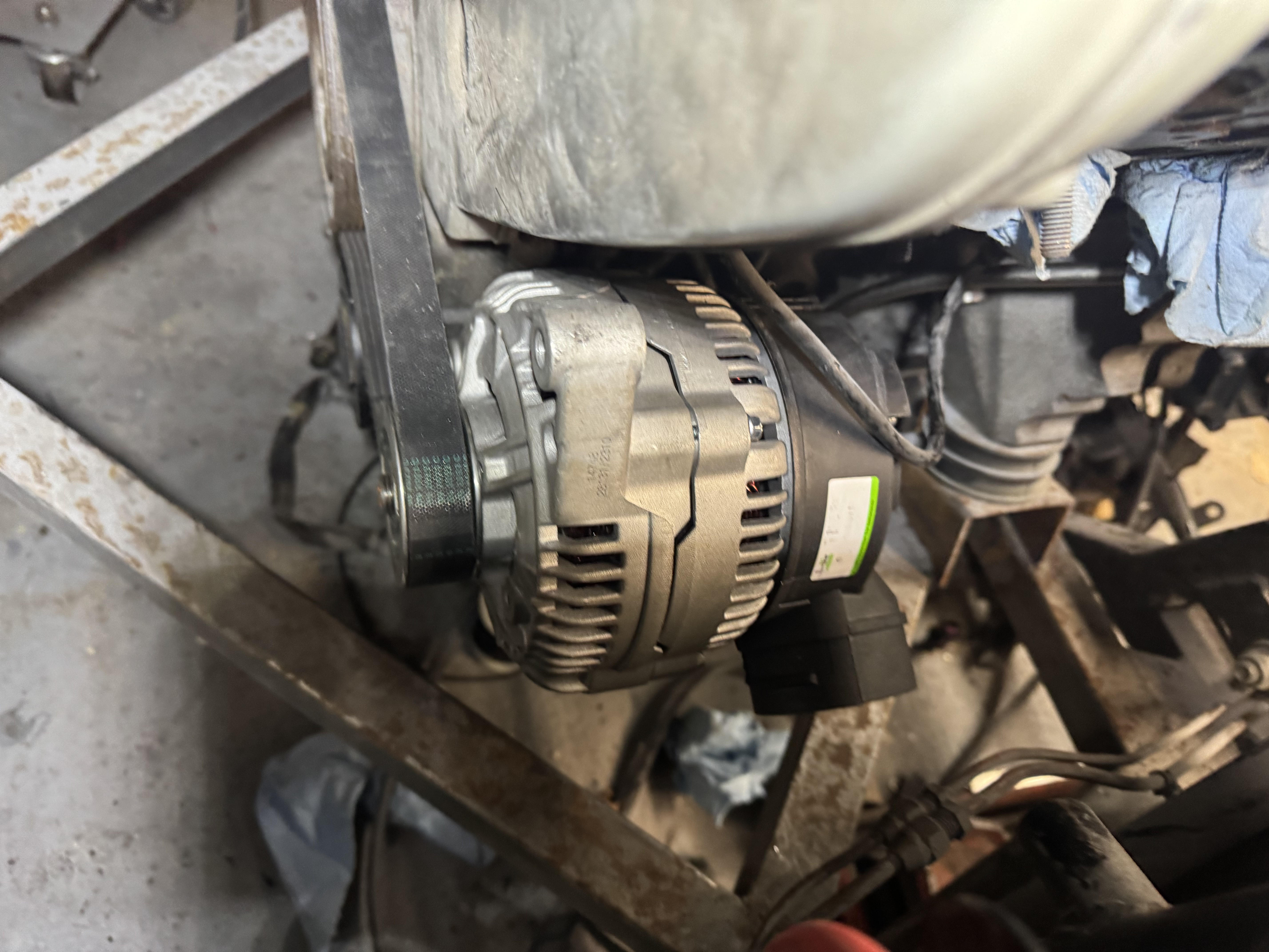
Top bracket and adjuster. Will clean it all up and powdercoat eventually.
 It is pretty much perfectly aligned. 🙂
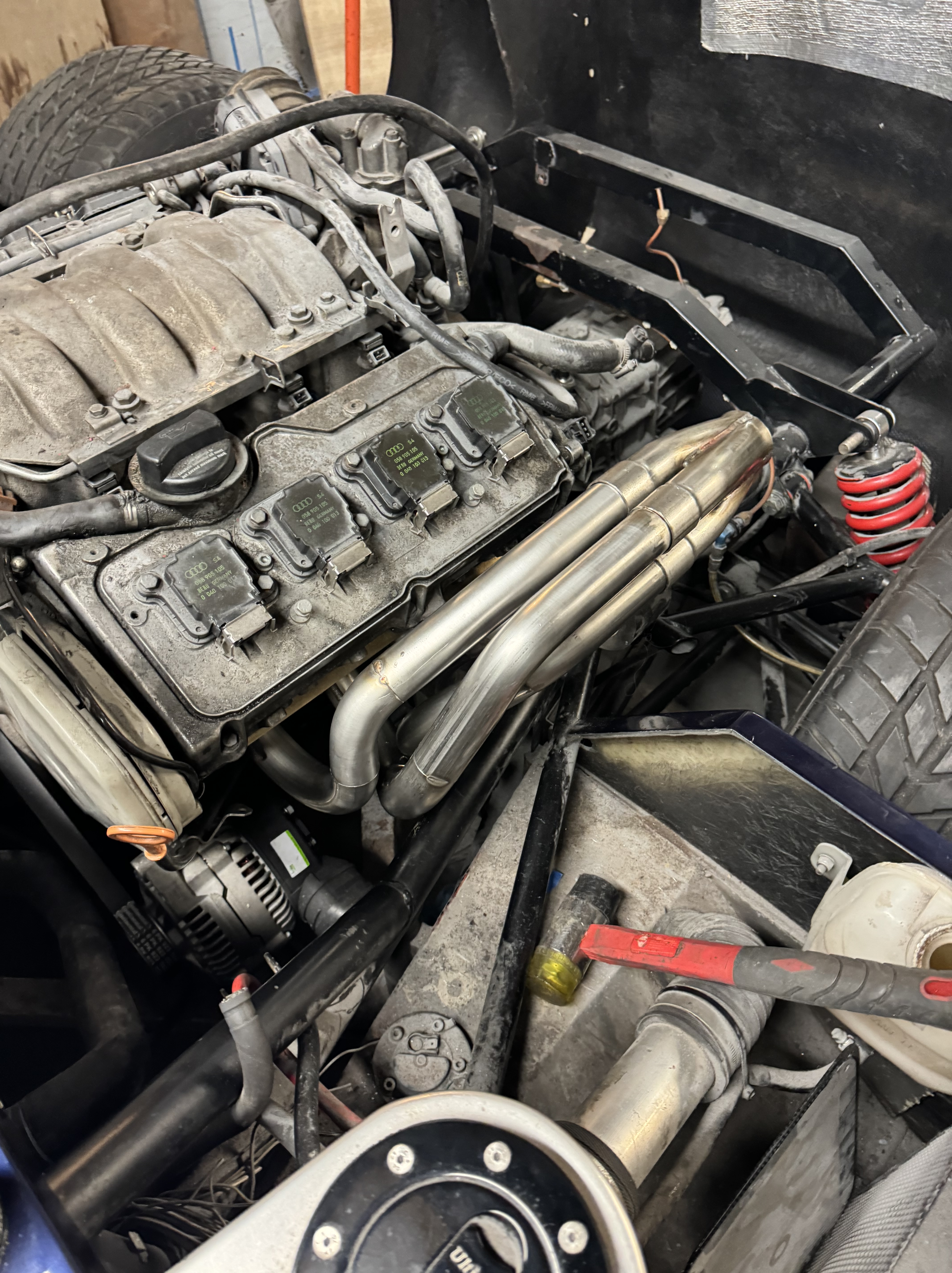
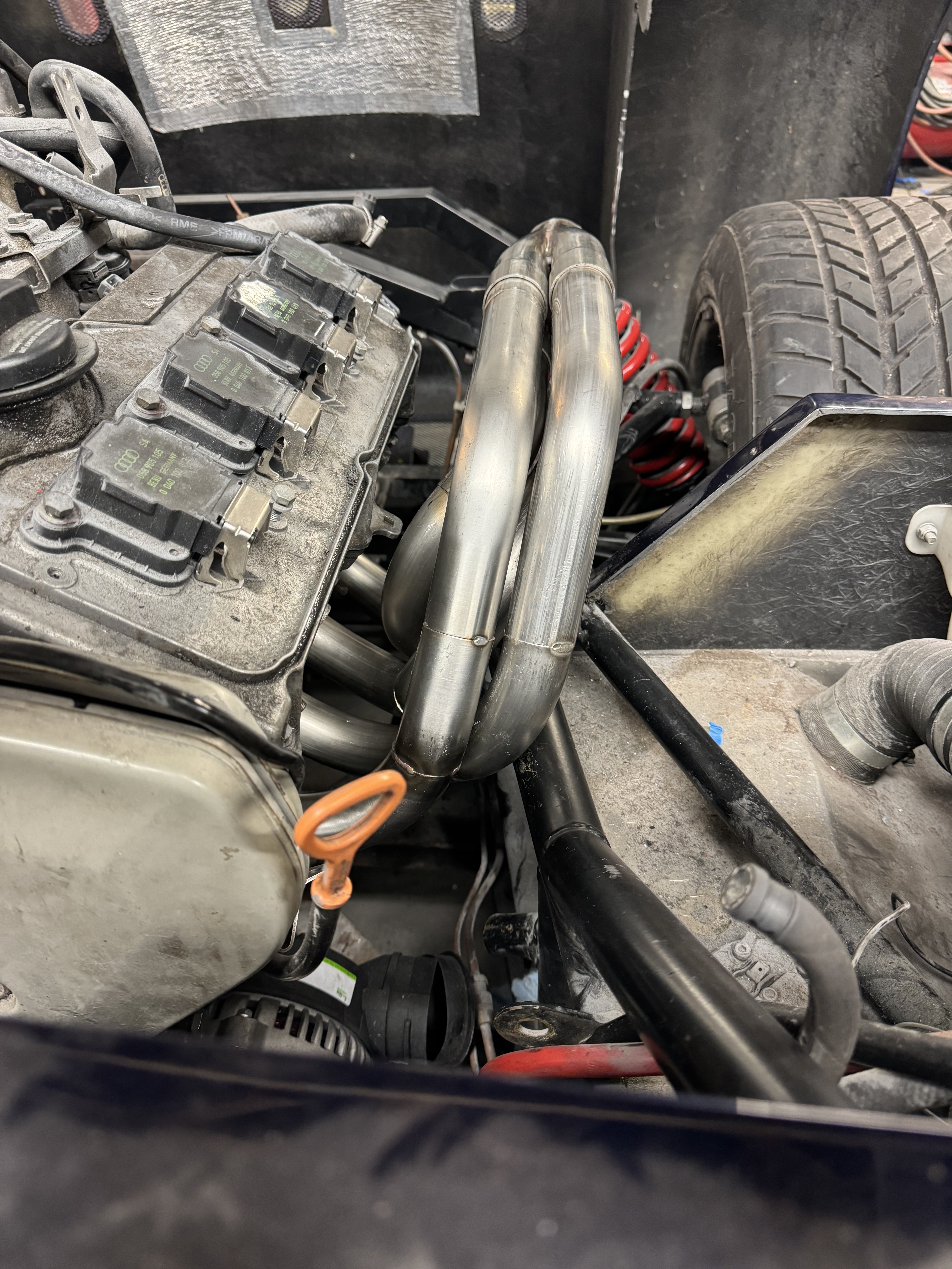
Exhausts
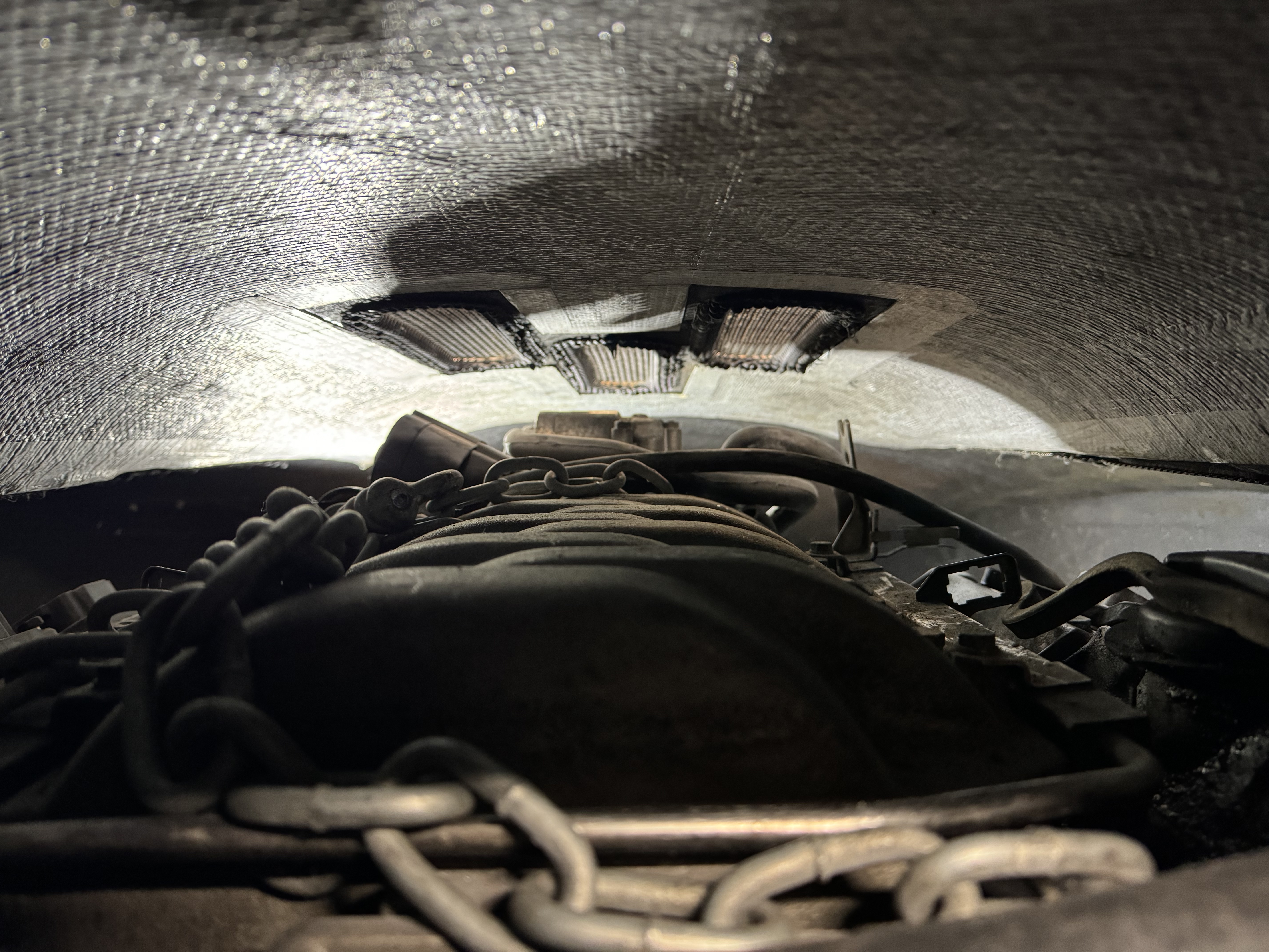
Exhausts next. I temporarily put the bodywork back on to check everything will fit OK since the spyder has the lowest of rear clam of all the models:
I tried to do something in CAD
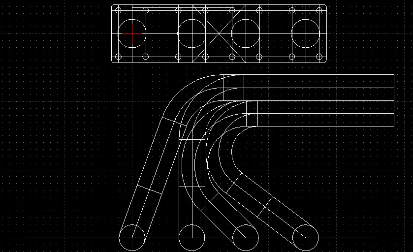
But quickly hit the limitations of 2D CAD, so just decided to have a go and crack on.
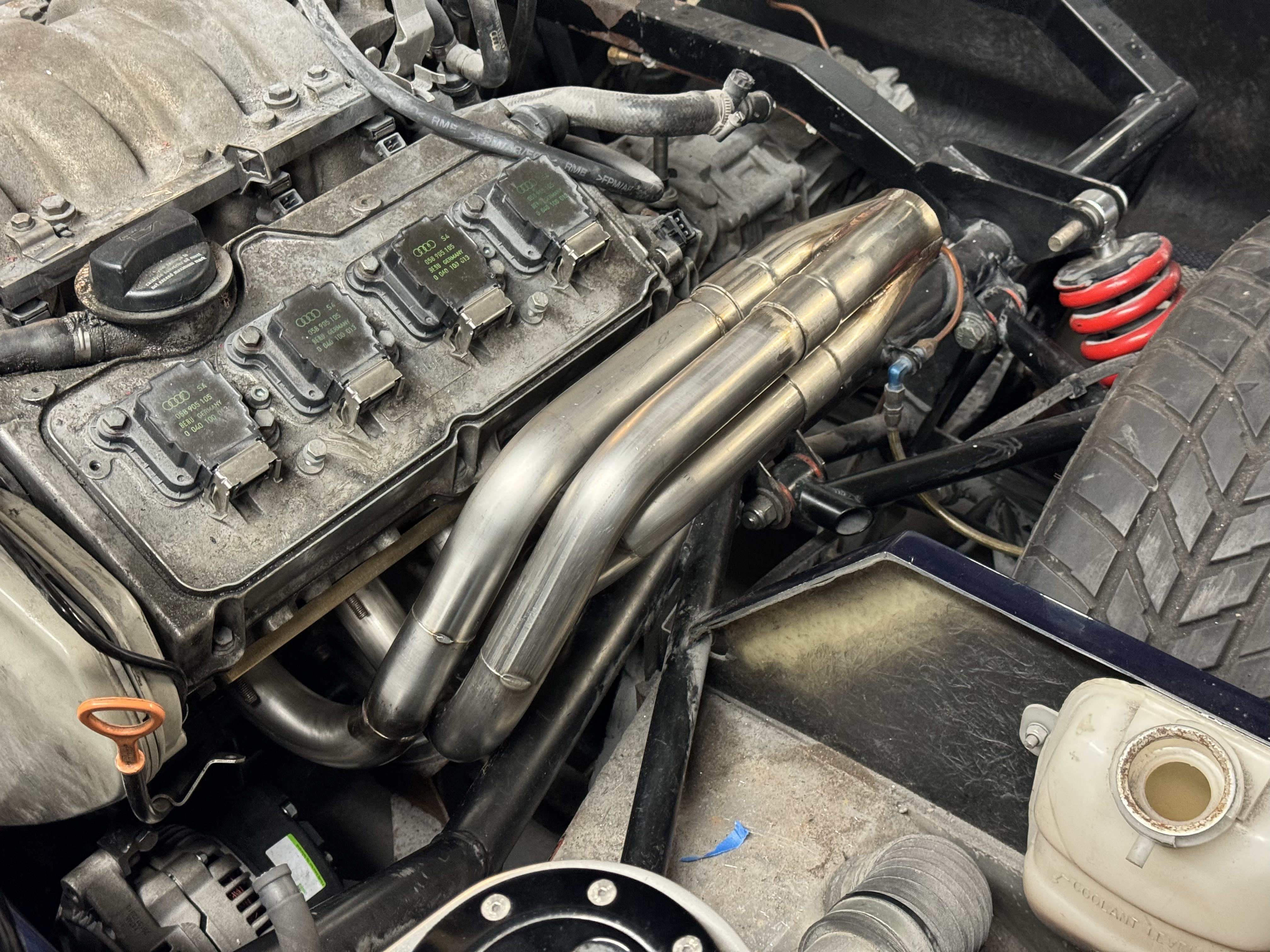
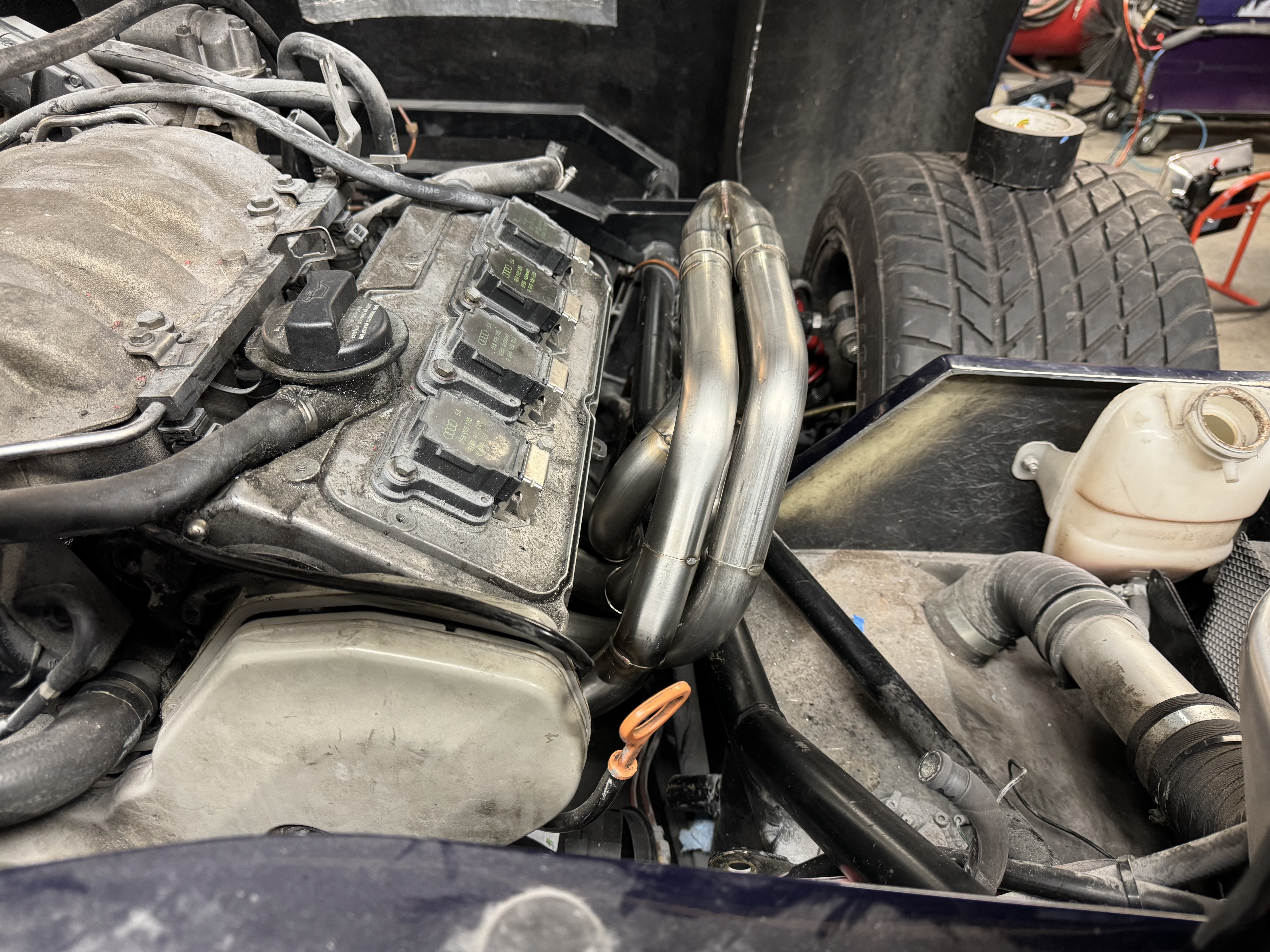
I’ve always viewed making headers as “dark magic”, it’s a tight fit to clear the chassis.
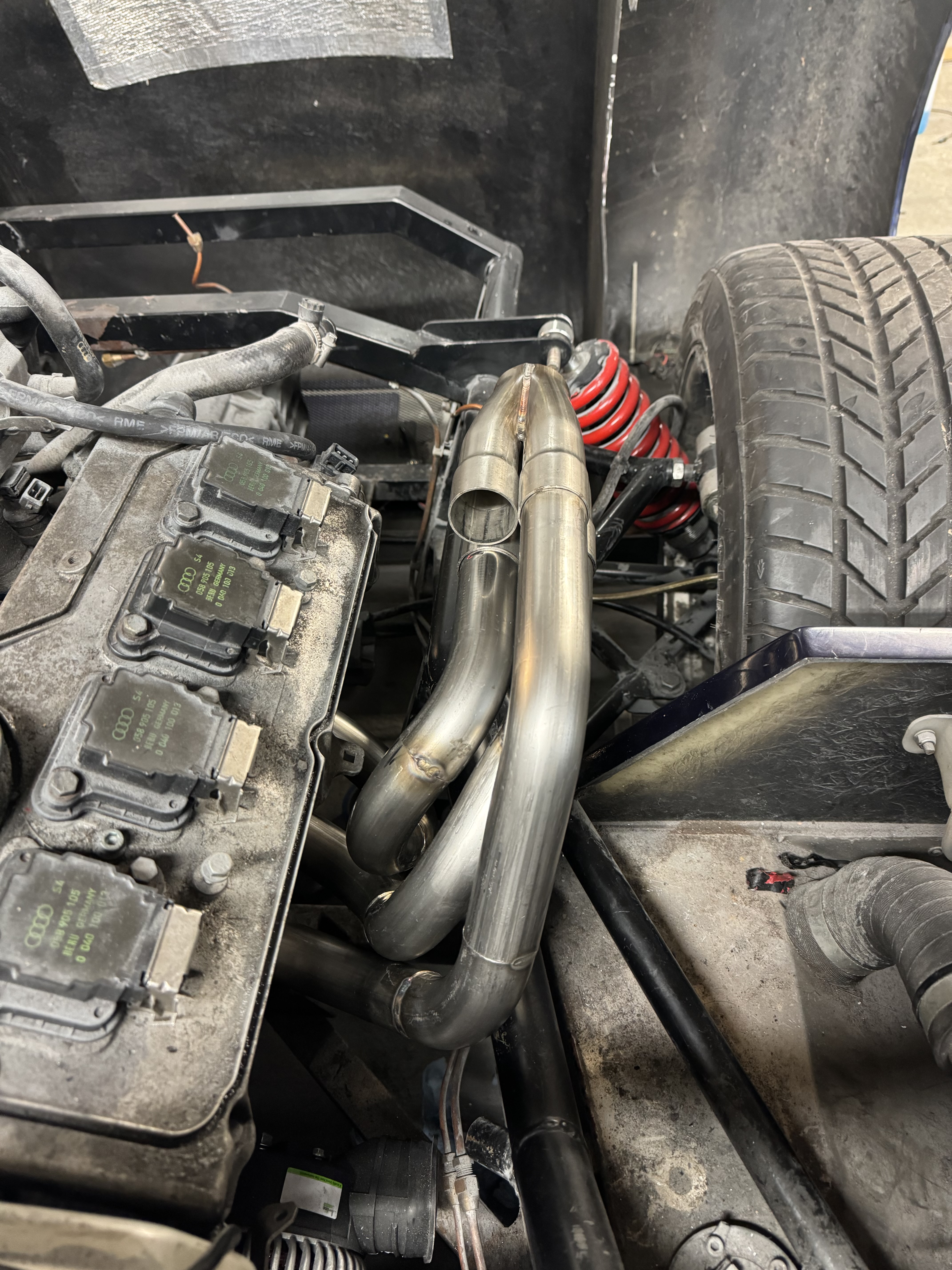
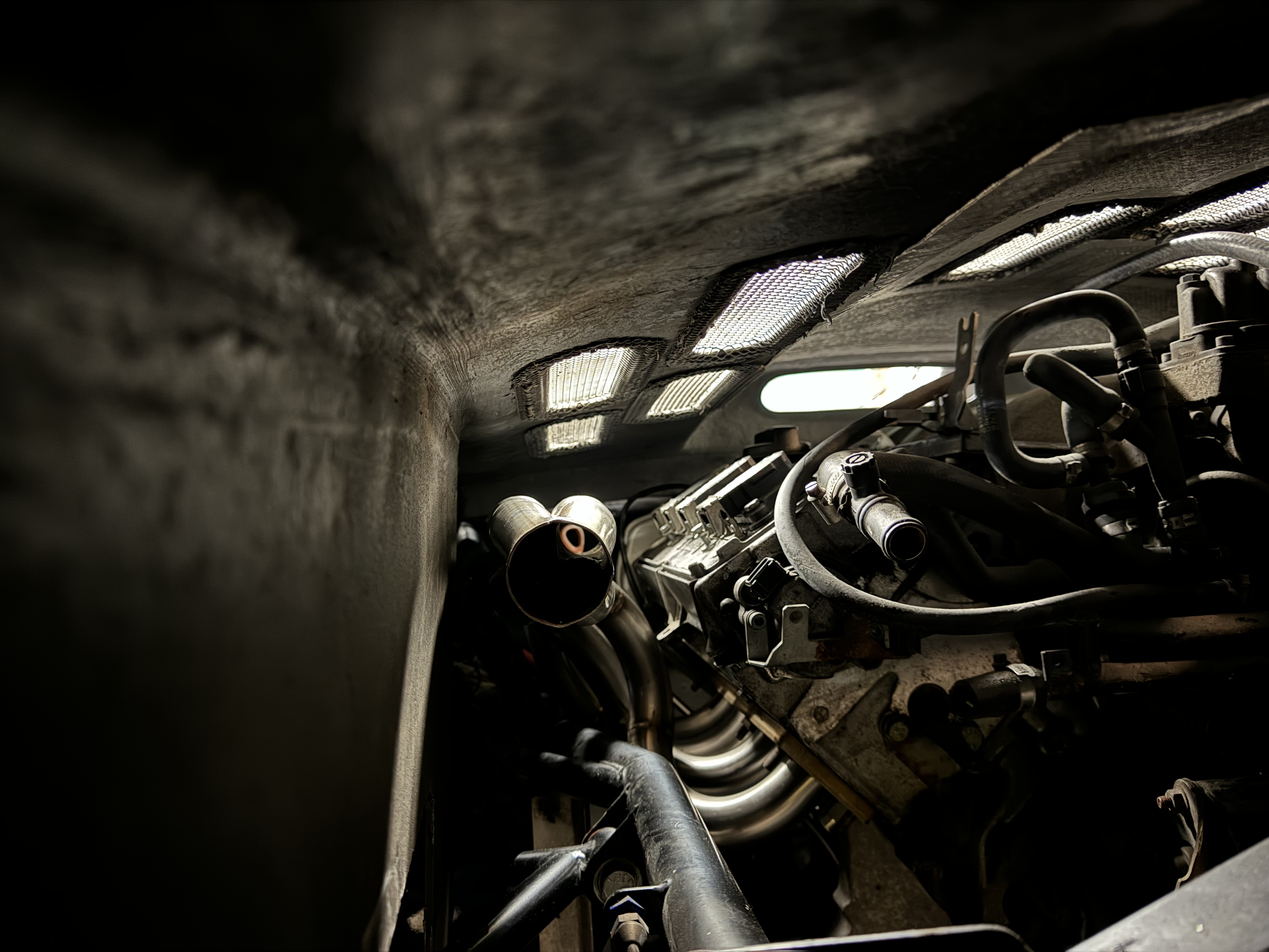
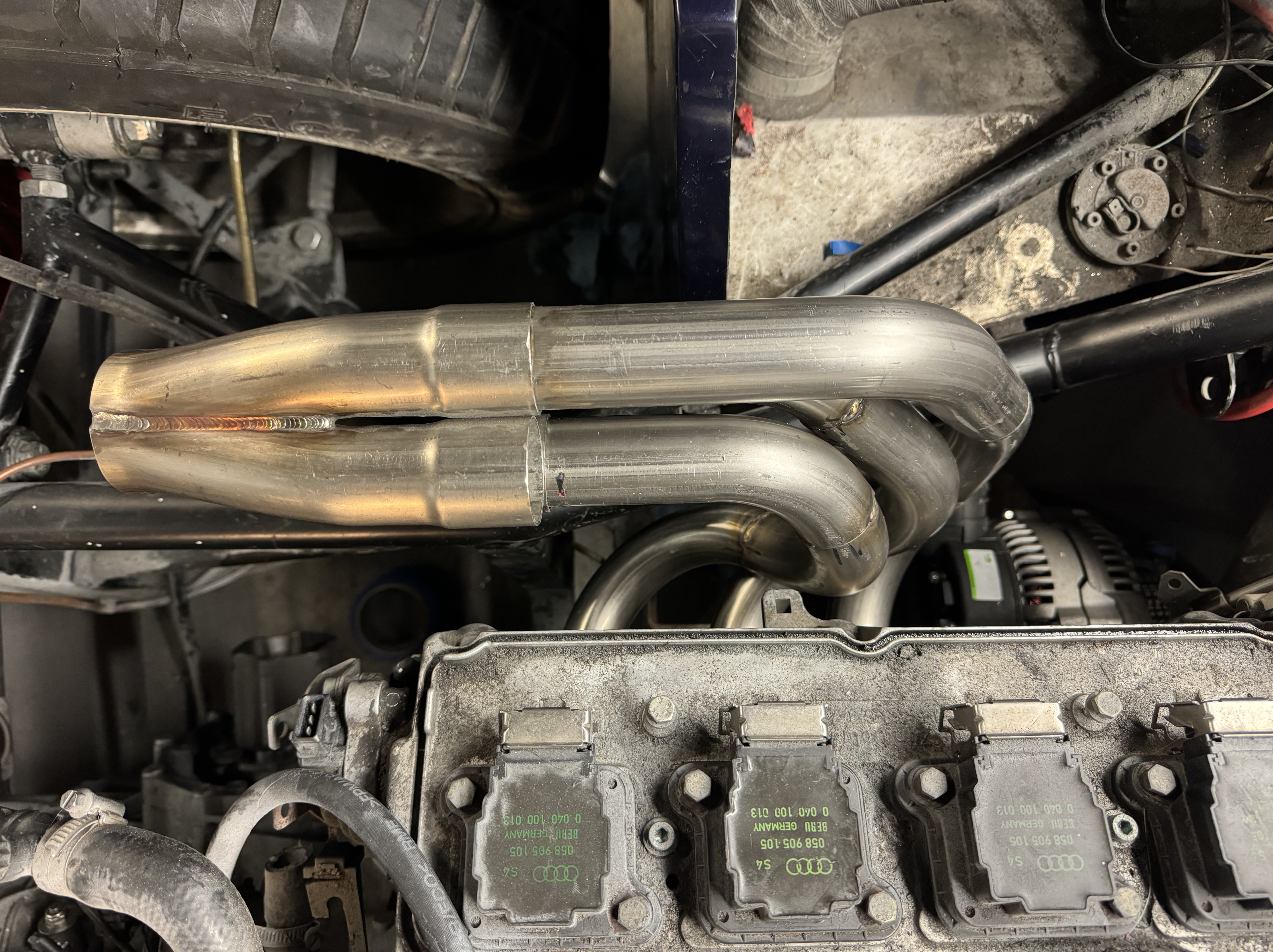 Am happy enough with the first three pipes, but the 4th was not so good:
I redid the final one on this side, I think it’s come out much better and tweaked the geometry of cylinder 3 to give a bit more clearance and level out the collector (not shown in this pic)
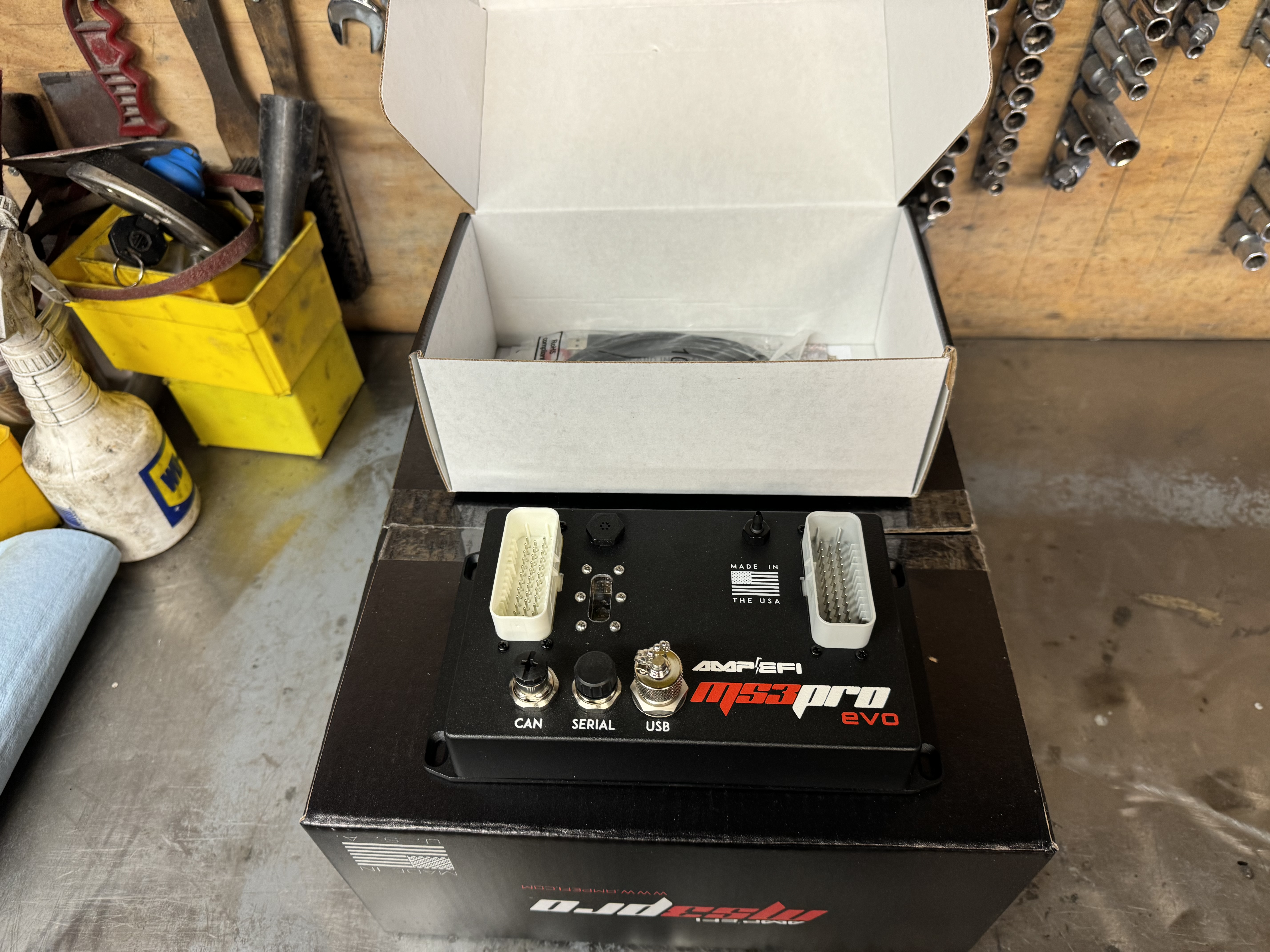
ECU
I have the ECU already. I’ve done a couple of megasquirts before (that I built myself), but this time while I’ve still gone megasquirt, I like the look of the prebuilt MS3. One the one hand, I’m being a bit pre-emptive, but on the other, it lets me think about “packaging”.
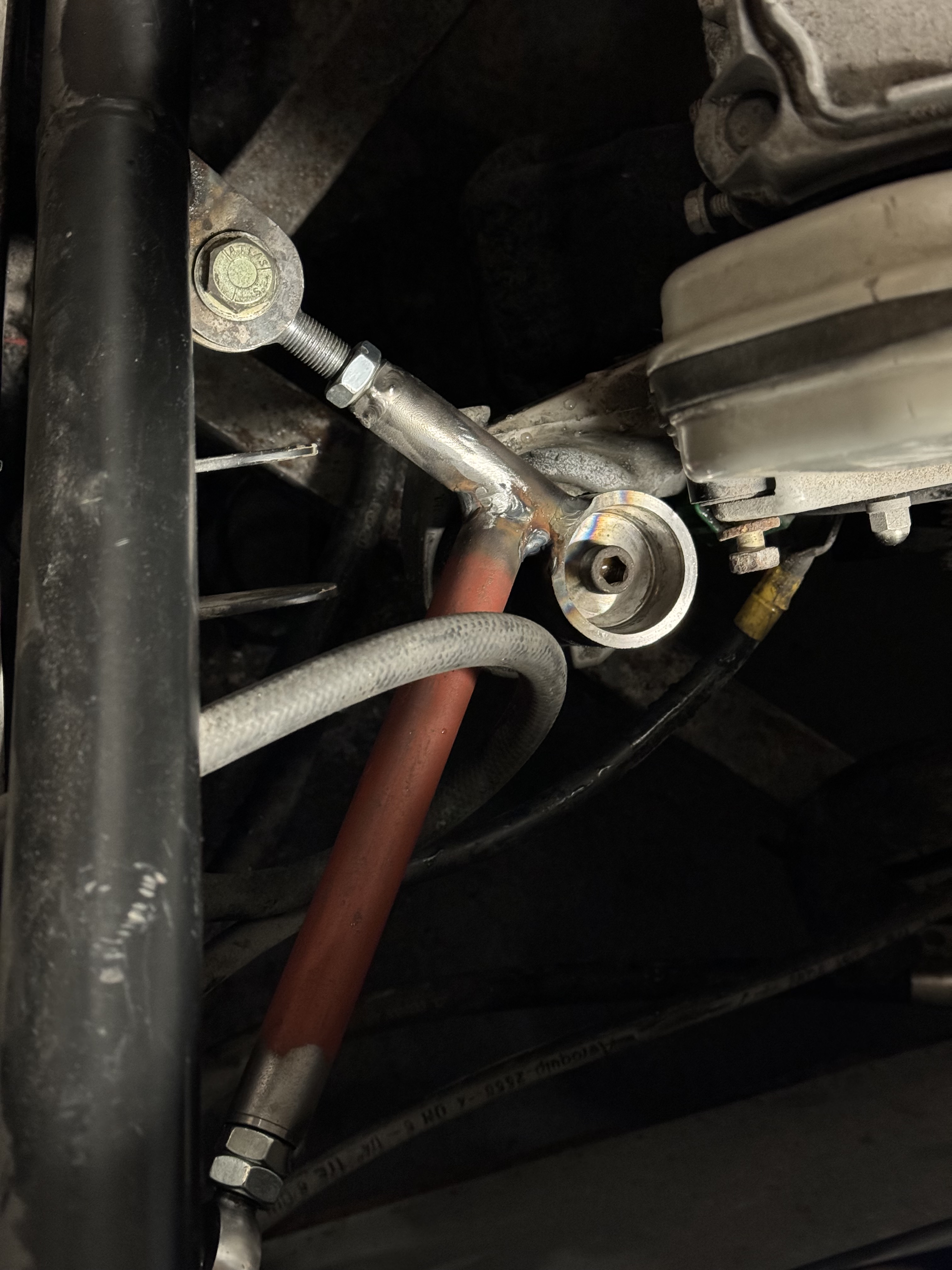
Tie Bar
Also made the engine tie bar:
That’s progress so far. Next I need to start the offside header, I think I have enough bits in stock, before I can start thinking about the rest of the exhaust system then.
